


Báo cáo hóa học: " A Real-Time GPP Software-Defined Radio Testbed for the Physical Layer of Wireless Standards"
lượt xem 4
download
 Download
Vui lòng tải xuống để xem tài liệu đầy đủ
Download
Vui lòng tải xuống để xem tài liệu đầy đủ
Tuyển tập báo cáo các nghiên cứu khoa học quốc tế ngành hóa học dành cho các bạn yêu hóa học tham khảo đề tài: A Real-Time GPP Software-Defined Radio Testbed for the Physical Layer of Wireless Standards
Bình luận(0) Đăng nhập để gửi bình luận!
Nội dung Text: Báo cáo hóa học: " A Real-Time GPP Software-Defined Radio Testbed for the Physical Layer of Wireless Standards"
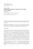
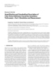
- EURASIP Journal on Applied Signal Processing 2005:16, 2664–2672 c 2005 Hindawi Publishing Corporation A Real-Time GPP Software-Defined Radio Testbed for the Physical Layer of Wireless Standards R. Schiphorst The Signals and Systems Group, Department of Electrical Engineering, Faculty of EEMCS, University of Twente, P.O. Box 217, 7500 AE Enschede, The Netherlands Email: r.schiphorst@utwente.nl F. W. Hoeksema The Signals and Systems Group, Department of Electrical Engineering, Faculty of EEMCS, University of Twente, P.O. Box 217, 7500 AE Enschede, The Netherlands Email: f.w.hoeksema@utwente.nl C. H. Slump The Signals and Systems Group, Department of Electrical Engineering, Faculty of EEMCS, University of Twente, P.O. Box 217, 7500 AE Enschede, The Netherlands Email: c.h.slump@utwente.nl Received 30 January 2004; Revised 23 September 2004 We present our contribution to the general-purpose-processor-(GPP)-based radio. We describe a baseband software-defined radio testbed for the physical layer of wireless LAN standards. All physical layer functions have been successfully mapped on a Pentium 4 processor that performs these functions in real time. The testbed consists of a transmitter PC with a DAC board and a receiver PC with an ADC board. In our project, we have implemented two different types of standards on this testbed, a continuous- phase-modulation-based standard, Bluetooth, and an OFDM-based standard, HiperLAN/2. However, our testbed can easily be extended to other standards, because the only limitation in our testbed is the maximal channel bandwidth of 20 MHz and of course the processing capabilities of the used PC. The transmitter functions require at most 714 M cycles per second and the receiver functions need 1225 M cycles per second on a Pentium 4 processor. In addition, baseband experiments have been carried out successfully. Keywords and phrases: software-defined radio, testbed, baseband, physical layer, HiperLAN/2, Bluetooth. 1. INTRODUCTION ideal software radio while being realizable with current-day technology. Such a system is called a software-defined radio New wireless communications standards do not replace old (SDR). ones; instead the number of standards keeps on increasing Software-defined radio has both advantages for and by now an abundance of standards already exists; see consumers and manufactures because current products Table 1. Moreover there is no reason to assume that this trend support only a fixed number of standards. Figure 1 shows will ever stop. Therefore the software-radio concept is emerg- the lifetime of products and wireless standards. One can see ing as a potential pragmatic solution: a software implemen- that products support a fixed number of standards and in tation of the user terminal able to dynamically adapt to the time new standards emerge and old ones disappear, making radio environment in which the terminal is located [1]. a product eventually obsolete. Because of the analog nature of the air interface, a soft- Software-defined radios on the other hand will enable ware radio will always have an analog front end. In an ideal consumers to upgrade their radio with new functionality, software radio, the analog-to-digital converter (ADC) and for example, required by new standards, just by software up- the digital-to-analog converter (DAC) are positioned directly dates, without the need for new hardware. Moreover, manu- after the antenna. Such an implementation is not feasible facturers can upgrade or improve functionality of consumer- due to the power that this device would consume and other owned products and SDR could result in shorter devel- physical limitations [2, 3]. It is therefore a challenge to de- opment time, cheaper production due to higher volumes. sign a system that preserves most of the properties of the
- A Real-Time GPP Software-Defined Radio Testbed 2665 Table 1: Overview of wireless standards [16]. Standard Frequency band Modulation type CT2 864/868 MHz GFSK CT2+ 944/948 MHz GFSK DECT 1880–1900 MHz GFSK PHS 1893–1920 MHz DQPSK 2402–2480 MHZ (North America) IEEE 802.15.4 GFSK 2412–2472 MHz (Europe) 2483 MHz (Japan) 2402–2480 MHz (North America and Europe) 2447–2473 MHz (Spain) GFSK Bluetooth 2448–2482 MHz (France) 2473–2495 MHz (Japan) 2402–2480 MHz (North America and Europe) 2447–2473 MHz (Spain) HomeRF GFSK 2448–2482 MHz (France) 2473–2495 MHz (Japan) 5150–5250 MHz (USA) IEEE 802.11a 5250–5350 MHz (USA) OFDM: 2/4/16/64 QAM 5725–5825 MHz (USA) 2410–2462 MHz (North America) IEEE 802.11b 2412–2472 MHz (Europe) GFSK/DBPSK/DQPSK/QPSK 2483 MHz (Japan) 5150–5250 MHz (USA) 5250–5350 MHz (USA) 5725–5825 MHz (USA) HiperLAN/2 5150–5350 MHz (Europe) OFDM: 2/4/16/64 QAM 5470–5725 MHz (Europe) 5725–5875 MHz (Europe) 5150–5250 MHz (Japan) 824–849 MHz 869–894 MHz CDMA: π /4 DQPSK IS-54/IS-136 1850–1910 MHz 1930–1990 MHz 824–849 MHz 869–894 MHz 1850–1910 MHz CDMA: QPSK/OQPSK IS-95 1930–1990 MHz 1920–1980 MHz (Asia only) 2110–2170 MHz (Asia only) 1920–1980 MHz 2110–2170 MHz CDMA: QPSK IMT-2000/UMTS 1900–1920 MHz 2010–2025 MHz
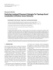
- 2666 EURASIP Journal on Applied Signal Processing Table 1: Continued. Standard Frequency band Modulation type 824–849 MHz 869–894 MHz 880–915 MHz 925–960 MHz GSM GMSK 1710–1785 MHz 1805–1880 MHz 1850–1910 MHz 1930–1990 MHz 810–826 MHz 940–956 MHz 1429–1441 MHz π/ 4 DQPSK PDC 1453–1465 MHz 1477–1489 MHz 1501–1513 MHz ··· Standard 7 Product V Product III Standard 6 Standards Standard 5 Standard 4 Product VI Standard 3 Standard 2 Standard 1 Time Product I Product II Product IV Figure 1: Standards support by products in time. and medium access control (MAC) layer as a transition area. Implementation Software ··· In our SDR project [4], we research whether the lowest layer, Protcols the physical layer, of wireless standards can be implemented Logical link control in software running on a general-purpose processor and es- Medium access control timate the costs of such an implementation with respect Physical layer Hardware to power consumption and computational power require- ments. Figure 2: Mapping of protocols in current designs on hardware/ So, we interpret SDR as an implementation technology software. which differs from the views in [1, 5], that is, flexible, univer- sal, radio systems at each layer of the OSI model from which manufacturers, network operators, and consumers can bene- However the downside of SDR will be power consumption as dedicated designs are more power efficient which is very fit. Our interpretation of SDR is more focussed on the phys- ical layer, an implementation technology, invisible for con- important for mobile applications. sumers. Moreover we want to investigate if we can use exist- ing processing capabilities (e.g., a notebook’s CPU) for dig- 2. SOFTWARE-DEFINED RADIO ital signal processing purposes, thereby possibly prolonging the lifetime of a device. This saves hardware and Moore’s law Figure 2 depicts the mapping in current radio designs of the different OSI1 layers on software/hardware. The physical will lower in time the computational load as a percentage of the computational capacity. layer is generally implemented in hardware and higher layers A flexible, all-standard, radio will always consume more are often software based with the logical link control (LLC) energy than a dedicated radio; thus the first application for a flexible radio; will be an application where power consump- 1 Open tion is less an issue, an example being a flexible radio in a system interconnection protocol model (OSI).
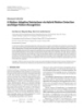
- A Real-Time GPP Software-Defined Radio Testbed 2667 concludes by presenting real-world measurements done with Notebook the testbed. Wideband DAC / CPU ADC analog front end 3. SDR BASEBAND TESTBED In the first phase of the project, we built two separate re- Figure 3: Project scope. ceivers [8] in order to gain knowledge. After the first phase, we concluded that a real-time software implementation of notebook. This application for SDR has three advantages. the physical layer functions of the transmitter and receiver First, we can use the processing capabilities of the general- on a Pentium 4 processor was possible. Therefore we started purpose processor for digital signal processing purposes. Sec- in the second phase of the project with a real-time software ond, in comparison to SDR for mobile phones, our demon- implementation of the Bluetooth and HiperLAN/2 receiver strator can consume much more power (in the order of 1 W). and transmitter. Third, a notebook is very suited for demonstration purposes. Although we show that a real-time software implementa- Table 1 gives an overview of important wireless stan- tion of the receiver (and transmitter) functionality is possible dards together with the used frequency bands and modula- using the notebook’s processor, it requires, besides process- tion type. It seems that each standard can be seen as a fam- ing power, a real-time operating system. Traditional operat- ily of standards, an example being GSM. Thus the number ing systems such as Windows or Linux are non-real time; for of existing standards that manufacturers have to support is example, the latency of the system is undefined and can be even larger than one would initially expect. However, there up to 100 milliseconds for Linux [9]. So it is possible that our receiver program misses a buffer and data is lost. How- are also similarities among them; the used frequency bands are between 0.8 and 6 GHz with dominant frequency bands ever, special patches can be applied to the Linux kernel for around the 0.8 GHz, 2 GHz, 2.4 GHz, and 5 GHz. In addi- example, which reduces this maximal latency to about 5 mi- croseconds [9].2 In our testbed, we use large sample buffers tion, three types of transceivers are used, phase modulation, OFDM (orthogonal frequency-division multiplexing), and of 100 milliseconds to avoid the influence of the operating CDMA (code-division multiple access) transceivers. system but additional research is needed to find the maximal In our SDR project, we decided not to focus on an all- allowable latency which is probably determined by the MAC standard radio but to start with a software-defined radio for layer. Furthermore, we have to investigate if this value can be wireless LAN standards first. The research is carried out by achieved in our testbed. So at the moment, our testbed can two chairs of the University of Twente: the IC-Design group only be used for continuous transmission of MAC bursts. which focusses on the RF part and the Signals and Systems 3.1. Functional architecture group focussing on the baseband part. At the project’s start we also defined the scope of the project: the physical layer Figure 4 depicts the functional architecture of the Bluetooth excluding error-correction encoding/decoding. Recent liter- transmitter and receiver. The first step in the transmitter is to ature [6] indicates, however, that especially error-correction embed the raw bits into MAC bursts which are then BPSK decoding (Viterbi algorithm) requires most of the computa- modulated at 1 Mbp. The BPSK symbols are filtered by a tional power in the lower layers of a system. Figure 3 sum- Gaussian lowpass filter and the filtered output is connected to marizes the design goal of our project, a notebook with a VCO that translates the amplitude variation into frequency wideband RF front end with a software implementation of variations. At the receiver side, the first step is to select the the physical layer. wanted Bluetooth channel and suppress all others which is Wireless LAN standards use phase modulation or OFDM performed both digitally and by the analog front end. This in the 2.4 GHz or 5 GHz frequency band, so we decided in is achieved by mixing the wanted channel to baseband and our project to combine an instance of a phase-modulation applying a lowpass filter. The next step is to demodulate the standard (Bluetooth) with an OFDM standard (Hiper- FM signal into an AM signal by taking the derivative of the LAN/2). Table 2 shows some characteristics of the physical phase. Because a frequency offset introduces an offset in the layer of both standards. HiperLAN/2 is a high-speed wire- AM signal, it has to be corrected before bit decision. less LAN (WLAN) standard using OFDM. Its physical layer is On the other hand, Figure 5 depicts the HiperLAN/2 very similar to the 802.11a standard. Bluetooth on the other physical layer architecture which is very different from the hand is a low-cost, low-speed standard, designed for replac- Bluetooth architecture one. The HiperLAN/2 transmitter ing fixed cables. Bluetooth uses continuous-phase modula- starts with mapping raw bits on BPSK, QPSK, 16-QAM, or tion, Gaussian frequency shift keying (GFSK) which is also 64-QAM symbols, depending on the used mode. In the next used by other standards such as HomeRF and DECT. step, the QAM symbols are mapped on data carriers and an This paper discusses only the digital baseband part of OFDM symbol is constructed by adding pilot carriers, ap- the project. More information about the total project can plying an inverse FFT, and adding a prefix, which results in be found in [7] or at the project’s website [4]. The rest of the paper is organized as follows. First the functional archi- tecture of the physical layer of both standards is discussed, 2 A HiperLAN/2 MAC frame has a Duration of 2 milliseconds and the which is followed by a description of the testbed. This paper shortest Bluetooth MAC frame is 0.625-millisecond long.
- 2668 EURASIP Journal on Applied Signal Processing Table 2: Some physical layer characteristics of Bluetooth and HiperLAN/2. Parameter Bluetooth HiperLAN/2 2.4–2.48 GHz 5.15–5.725 GHz Band Channel spacing 1 MHz 20 MHz Modulation GFSK OFDM: BPSK/QPSK/16 QAM/64 QAM 172.8–723.2 kbps Nominal bit rate (no FEC) 12–72 Mbps Synchronization Frequency r [k ] Raw Lowpass FM-to-AM Mixing offset Decision t [k ] converter bits Raw MAC burst filter BPSK Gaussian correction VCO bits generation modulator filter Channel selection (a) (b) Figure 4: Functional architecture of the Bluetooth (a) transmitter and (b) receiver (functional layer excluding error-correction encod- ing/decoding). r [k ] Control Synchronization/parameter estimation Raw QAM 64-point Prefix insertion bits mapping IFFT t [k ] Phase offset Frequency Raw QAM 64-point Channel offset estimation/ Preambles equalization demapping bits FFT correction correction (a) (b) Figure 5: Functional architecture of the HiperLAN/2 (a) transmitter and (b) receiver (functional layer excluding error-correction encod- ing/decoding). r [k ] Sample rate Synchronization/parameter estimation reduction Frequency Phase QAM Channel 64-point offset offset equalization demodulation FFT correction correction HiperLAN/2 mode Raw bits Bluetooth mode Frequency Lowpass offset Mixing MAP receiver filter correction Figure 6: Functional architecture of the Bluetooth-enabled HiperLAN/2 receiver (functional layer excluding error-correction encod- ing/decoding). and detecting and correcting the phase offset by using the a 20-MSPS signal. MAC bursts are then created by adding special symbols, preambles, to the start of the MAC burst. pilot tones. The output is QAM symbols which have to be The HiperLAN/2 receiver starts by searching for the start demapped into raw bits. of an MAC burst. If it is found, it estimates the frequency Although the functional architecture of both standards offset and channel parameters. After these steps, the data is very different, we have successfully integrated the Blue- OFDM symbols can be demodulated by first correcting the tooth receiver functionality into the HiperLAN/2 receiver frequency offset, performing an FFT, correcting the channel, [10] (Figure 6) by using a (simplified) maximum a posteriori
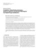
- A Real-Time GPP Software-Defined Radio Testbed 2669 I I I cPCI-7300 cPCI-7300 Pentium 4 Pentium 4 ADCs DACs DAC ADC SRC Analog 20 MSPS 20 MSPS FSB800 FSB533 PC board PC board 2.8 GHz 2.4 GHz Q Q Q Transmitter Receiver Figure 7: Component architecture of the SDR testbed. (a) (b) Figure 8: (a) DAC board and (b) ADC board. probability (MAP) receiver which is a more advanced Blue- but in the near future we will conduct RF experiments, in which the analog transmitter signal is upconverted to the 2.4 tooth demodulation algorithm [11]. In this testbed, however, we did not implement this receiver (yet) but used instead a or 5 GHz frequency band. The RF signal will then be con- conventional receiver such as the one depicted in Figure 4. nected to the analog SDR front end [7] whose output signal is fed to the ADC board. 3.2. Testbed setup 4. MEASUREMENTS IN THE TESTBED Figure 7 shows the component architecture of our SDR testbed. The testbed consists of four components; a trans- 4.1. User scenarios mitter PC, a DAC PC board (Figure 8a), a receiver PC, and For both standards, Bluetooth and HiperLAN/2, we derived an ADC PC board (Figure 8b). a user scenario to estimate and measure the computational The transmitter PC continuously generates HiperLAN/2 requirements, assuming continuous transmission. This sce- or Bluetooth MAC bursts which are sent in real time to the nario can be compared with a realistic scenario that includes DAC board at 20 MSPS by using an Adlink cPCI-7300 dig- the influences of the higher OSI layers on the physical layer. ital I/O PCI card. This DAC board converts the digital sig- nal into a complex analog baseband signal. The ADC board 4.1.1. Bluetooth user scenario samples the analog signal with 80 MSPS and the onboard The Bluetooth symbol duration is 1 microsecond and data Intersil ISL5416 programmable down-converter decimates is transmitted in time slots with a duration of 625 microsec- the digital signal into a complex 20-MSPS signal in Hiper- onds [12]. For estimating computational requirements, we LAN/2 mode and into a 5-MSPS signal (including mixing assume maximal transfer rate. In this mode, Bluetooth uses the wanted channel to baseband) for Bluetooth. This signal is a packet which spans 5 time slots and 1 time slot is used for transported to the receiver PC by using another Adlink cPCI- uplink communication. 7300 digital I/O PCI card. The receiver PC performs all de- modulation functions and demodulates the MAC bursts in 4.1.2. HiperLAN/2 user scenario real time. A HiperLAN/2 MAC frame consists of 5 parts and has a max- At this moment in time, the analog signal of the DAC imal duration of 2 milliseconds [13]. We assume that all parts board is directly connected to the input of the ADC board
- 2670 EURASIP Journal on Applied Signal Processing Table 3: Computational load of the Bluetooth receiver and transmitter functions mapped on a Pentium 4 processor. TX function M operations/s M cycles/s RX function M operations/s M cycles/s MAC burst generation 1 1 Integer-to-float conversion 20 88 GFSK modulation 2100 440 FM-to-AM conversion 75 261 Float-to-integer conversion 80 320 Synchronization 1 27 Frequency offset correction 1 Not implemented Bit decision 3 33 Total 2181 714 Total 100 437 Table 4: Computational load of the HiperLAN/2 receiver and transmitter functions mapped on a Pentium 4 processor for 64-QAM mode. TX function M operations/s M cycles/s RX function M operations/s M cycles/s QAM mapping 38 85 Integer-to-float conversion 80 351 IFFT 230 128 Synchronization and Float-to-integer conversion 80 215 parameter estimation 4 60 Frequency offset correction 39 120 FFT 230 318 Channel equalization 39 79 Phase offset detection and correction 40 127 64-QAM demapping 77 204 Total 348 500 Total 509 1225 have equal duration and that we have to demodulate 2 parts particular function is influenced by many parameters such as (one common and one user part). cache misses, memory alignment, and so forth. It is for that reason that we used average values in these time measure- 4.2. Computational power requirements ments. The number of cycles required for the whole receiver or transmitter function (total values) is measured separately We used the user scenarios of both standards for the im- and not determined by summing up all individual compo- plementation of the transmitter and receiver. This section nents. presents the required computational power for each function that is mapped on the Pentium 4 processor and the number 4.2.3. Results of cycles needed by the CPU for computing the function. Table 3 lists, for each function of the Bluetooth transmitter and receiver, the number of required operations (multipli- 4.2.1. Software cations, additions, etc.) and how much cycles this function needs on a Pentium 4 processor. Especially the GFSK mod- The source code of the Bluetooth and HiperLAN/2 transmit- ulation, conversion to fixed-point numbers of the Bluetooth ter and receiver is written in C and compiled with the Intel transmitter, and FM to AM conversion of the receiver require compiler 7.1 under Linux, using floating-point precision be- most of the cycles. In the GFSK modulation function, a 60- cause floating-point operations are as fast as fixed-point op- tap Gaussian filter is used that requires 1000 million addi- erations on a Pentium 4 processor. Moreover, we used the tions plus multiplications per second. In our implementa- open-source FFTW library [14] for computing the inverse tion, we replaced this filter by lookup tables as the output FFT and FFT. As a DAC requires fixed-point numbers, the value of the filter depends on the last 4 BPSK symbols. This transmitter has to convert the floating-point numbers into optimalization reduces the amount of computations signifi- fixed point. The receiver, on the other hand, receives fixed- cantly. point numbers from the ADCs, so it has to do the inverse Table 4 shows the number of required operations and process. It was observed that these conversions take a long cycles for each function of the transmitter and receiver for time to compute and therefore special SSE instructions [15] HiperLAN/2. are used for acceleration. Computational intensive parts are the conversion to floating-point precision, FFT and 64-QAM demapping in 4.2.2. Time measurement method the receiver, and conversion to fixed-point numbers in the Time measurements were performed on a Pentium 4 pro- transmitter. Moreover, the HiperLAN/2 transmitter requires cessor at 2.8 GHz by counting the number of cycles for each less computational power than the Bluetooth transmitter, al- function. A Pentium 4 processor is a very complex design though more bits are transmitted by the first one. The Hiper- and therefore the number of cycles needed for computing a LAN/2 receiver requires on the other hand more cycles per
- A Real-Time GPP Software-Defined Radio Testbed 2671 second than the Bluetooth receiver, but the latter one oper- [7] V. J. Arkesteijn, R. Schiphorst, F. W. Hoeksema, E. A. M. Klumperink, B. Nauta, and C. H. Slump, “A combined re- ates also at a much lower sample rate. ceiver front-end for Bluetooth and HiperLAN/2,” in Proc. 4th PROGRESS Workshop on Embedded Systems and Software, 4.2.4. Experiments Nieuwegein, the Netherlands, October 2003. [8] V. J. Arkesteijn, R. Schiphorst, F. W. Hoeksema, E. A. M. Baseband experiments have been performed with the setup Klumperink, B. Nauta, and C. H. Slump, “A software-defined in Figure 7. In HiperLAN/2 mode, successful transmission radio test-bed for WLAN front ends,” in Proc. 3rd PROGRESS and reception of continuously transmitted MAC bursts is Workshop on Embedded Systems and Software, Utrecht, the achieved. For Bluetooth mode, however, baseband experi- Netherlands, October 2002. ments still have to be carried out but we do not expect prob- [9] I. Ripoll, P. Pisa, L. Abeni, et al., “Deliverable D1.1- lems as HiperLAN/2 is more demanding. RTOS analysis,” http://www.mnis.fr/opensource/ocera/rtos/, 2002. [10] R. Schiphorst, F. W. Hoeksema, and C. H. Slump, “A Bluetooth-enabled HiperLAN/2 receiver,” in Proc. IEEE 58th 5. CONCLUSIONS Vehicular Technology Conference (VTC ’03), vol. 5, pp. 3443– This paper describes a software-defined radio testbed for 3447, Orlando, Fla, USA, October 2003. [11] R. Schiphorst, F. W. Hoeksema, and C. H. Slump, “A (sim- wireless LAN standards. The physical layer of the Hiper- plified) Bluetooth maximum a posteriori probability (MAP) LAN/2 standard has been implemented in software running receiver,” in Proc. IEEE 4th Signal Processing Advances in Wire- real time on a normal PC and baseband experiments have less Communications (SPAWC ’03), pp. 160–164, Rome, Italy, verified the system. However, literature [6] shows that for June 2003. HiperLAN/2, one of the most demanding parts is the FEC [12] BluetoothSIG, Specification of the Bluetooth System-Core, coding and FEC decoding (e.g., Viterbi algorithm) which we Technical Specification Version 1.1, ‘Bluetooth SIG’, February did not implement in the project. Additional research has 2001. [13] ETSI, Broadband Radio Access Networks (BRAN); HIPERLAN to be carried out if this holds also for a Pentium 4 imple- Type 2; Physical (PHY) layer, Technical Specification ETSI TS mentation and whether this limits a GPP-based software- 101 475 V1.2.2 (2001–2002), ETSI, February 2001. defined radio. Moreover, further research focusses on in- [14] http://www.fftw.org/. creasing functionality of our testbed, such as implementation [15] Tommesani.com, MMX/SSE/SSE2 primer http://www. of other standards and performing RF experiments. tommesani.com, 2003. [16] http://www.semiconductors.philips.com/comms. ACKNOWLEDGMENTS R. Schiphorst received his M.S. degree in We thank our colleagues from the IC-Design Group for their electrical engineering from the University of Twente in 2000 for his research on software- work on the analog part of the front end and for interesting defined radio. In September 2000, he joined discussions. Moreover, we thank Henny Kuipers and Geert- the Signal and Systems Group of the Uni- Jan Laanstra for building the DAC and ADC boards. This re- versity of Twente as a Ph.D. student to con- search is supported by the PROGram for Research on Em- tinue his research on software-defined ra- bedded Systems & Software (PROGRESS) of the Dutch Or- dio. His research interests include the design ganization for Scientific Research NWO, the Dutch Ministry and analysis of the digital part of software- of Economic Affairs, and the Technology Foundation STW. defined radios. In September 2004, he fin- ished his Ph.D. thesis and he is now working as a Research Scientist REFERENCES in the same chair. [1] J. Mitola III, Software Radio Architecture: Object-Oriented F. W. Hoeksema studied electrical engineer- Approaches to Wireless Systems Engineering, John Wiley & ing at the University of Twente. After his Sons, New York, NY, USA, 2000. graduation in 1987, he joined Philips Re- [2] R. H. Walden, “Performance trends for analog to digital con- search Laboratories in Eindhoven and con- verters,” IEEE Commun. Mag., vol. 37, no. 2, pp. 96–101, 1999. tributed to (pre JPEG) still image picture [3] V. J. Arkesteijn, E. A. M. Klumperink, and B. Nauta, “An coding and CCD sensor modeling. In 1998, analogue front-end architecture for software defined radio,” he joined the Department of Electrical En- in Proc. 13th Annual Workshop on Circuits, Systems and Sig- gineering at the University of Twente. In nal Processing (ProRISC ’02), Veldhoven, the Netherlands, the TIOS/TSS Group, he worked in the field November 2002. of image coding for ATM networks and at [4] The Bluetooth-HiperLAN/2 SDR receiver project website, performance measurements for BISDN systems (ACTS INSIGNIA http://www.sas.el.utwente.nl/home/SDR/. Project). In 2001, he switched to the Signals and Systems (SAS) [5] W. Tuttlebee, Software Defined Radio: Origins, Drivers and In- Group to participate in projects that focus on digital signal pro- ternational Perspectives, John Wiley & Sons, New York, NY, cessing for radio systems: the PROGRESS SDR Project, the Free- USA, 2002. band AWGN Project, and recently the Freeband AAF Project. His [6] K. Masselos, S. Blionas, and T. Rautio, “Reconfigurability re- current interest is in design and implementation of (digital) signal quirements of wireless communication systems,” in Proc. IEEE processing functions for radio systems and especially in parameter Workshop on Heterogeneous Reconfigurable Systems-on-Chip (SOC ’04), Hamburg, Germany, 2004. estimation for communication system purposes.
- 2672 EURASIP Journal on Applied Signal Processing C. H. Slump received the M.S. degree in electrical engineering from Delft University of Technology, Delft, The Netherlands in 1979. In 1984, he obtained his Ph.D. degree in physics from the University of Gronin- gen, The Netherlands. From 1983 to 1989, he was employed at Philips Medical Systems in Best as Head of a predevelopment group on medical image processing. In 1989, he joined the Signal and Systems Group of the University of Twente, Enschede, The Netherlands. His main re- search interest is in digital signal processing, including realization of algorithms in VLSI.
CÓ THỂ BẠN MUỐN DOWNLOAD

-
Báo cáo hóa học: "Research Article Detecting and Georegistering Moving Ground Targets in Airborne QuickSAR via Keystoning and Multiple-Phase Center Interferometry"
 11 p |
  116
|
116
|  7
7
-
Báo cáo hóa học: "Research Article Are the Wavelet Transforms the Best Filter Banks for Image Compression?"
7 p | 120
| 7
-
Báo cáo hóa học: " Research Article Practical Quantize-and-Forward Schemes for the Frequency Division Relay Channel"
11 p | 114
| 6
-
Báo cáo hóa học: " Research Article Breaking the BOWS Watermarking System: Key Guessing and Sensitivity Attacks"
8 p | 104
| 6
-
Báo cáo hóa học: " Research Article A Fuzzy Color-Based Approach for Understanding Animated Movies Content in the Indexing Task"
17 p | 108
| 6
-
Báo cáo hóa học: "Research Article Cued Speech Gesture Recognition: A First Prototype Based on Early Reduction"
19 p | 116
| 6
-
báo cáo hóa học:" Recombinant bromelain production in Escherichia coli: Process optimization in shake flask culture by Response Surface Methodology"
34 p | 96
| 6
-
Báo cáo hóa học: "Research Article Color-Based Image Retrieval Using Perceptually Modified Hausdorff Distance"
10 p | 97
| 5
-

Báo cáo hóa học: " Yeast expressed recombinant Hemagglutinin protein of Novel H1N1 elicits neutralising antibodies in rabbits and mice"
29 p | 76
| 5
-
Báo cáo hóa học: " Research Article Some Geometric Properties of Sequence Spaces Involving Lacunary Sequence"
8 p | 94
| 5
-
Báo cáo hóa học: "Research Article Exploring Landmark Placement Strategies for Topology-Based Localization in Wireless Sensor Networks"
12 p | 118
| 5
-
Báo cáo hóa học: " Research Article A Motion-Adaptive Deinterlacer via Hybrid Motion Detection and Edge-Pattern Recognition"
10 p | 93
| 5
-
Báo cáo hóa học: "Research Article Probabilistic Global Motion Estimation Based on Laplacian Two-Bit Plane Matching for Fast Digital Image Stabilization"
10 p | 112
| 4
-

báo cáo hóa học:" Sparse correlation matching-based spectrum sensing for open spectrum communications"
43 p | 74
| 4
-
Báo cáo hóa học: "Research Article On the Generalized Favard-Kantorovich and Favard-Durrmeyer Operators in Exponential Function Spaces"
12 p | 102
| 4
-
Báo cáo hóa học: " Research Article Hilbert’s Type Linear Operator and Some Extensions of Hilbert’s Inequality"
10 p | 77
| 4
-
Báo cáo hóa học: "Research Article Quantification and Standardized Description of Color Vision Deficiency Caused by"
9 p | 120
| 4
-
Báo cáo hóa học: " Cytopathic Mechanisms of HIV-1"
22 p | 78
| 4


Chịu trách nhiệm nội dung:
Nguyễn Công Hà - Giám đốc Công ty TNHH TÀI LIỆU TRỰC TUYẾN VI NA
LIÊN HỆ
Địa chỉ: P402, 54A Nơ Trang Long, Phường 14, Q.Bình Thạnh, TP.HCM
Hotline: 093 303 0098
Email: support@tailieu.vn
Giấy phép Mạng Xã Hội số: 670/GP-BTTTT cấp ngày 30/11/2015 Copyright © 2022-2032 TaiLieu.VN. All rights reserved.

