


Báo cáo hóa học: " Research Article Distributed Cooperative Precoding with Power Control for Cellular Systems with Correlated Antennas at the Receiver"
lượt xem 7
download
 Download
Vui lòng tải xuống để xem tài liệu đầy đủ
Download
Vui lòng tải xuống để xem tài liệu đầy đủ
Tuyển tập báo cáo các nghiên cứu khoa học quốc tế ngành hóa học dành cho các bạn yêu hóa học tham khảo đề tài: Research Article Distributed Cooperative Precoding with Power Control for Cellular Systems with Correlated Antennas at the Receiver
Bình luận(0) Đăng nhập để gửi bình luận!
Nội dung Text: Báo cáo hóa học: " Research Article Distributed Cooperative Precoding with Power Control for Cellular Systems with Correlated Antennas at the Receiver"
- Hindawi Publishing Corporation EURASIP Journal on Advances in Signal Processing Volume 2011, Article ID 706212, 12 pages doi:10.1155/2011/706212 Research Article Distributed Cooperative Precoding with Power Control for Cellular Systems with Correlated Antennas at the Receiver Vinosh Babu James J.,1, 2 Bhaskar Ramamurthi,1, 2 and Ganesh Venkatraman2 1 Department of Electrical Engineering, The Indian Institute of Technology Madras, Guindy, Chennai 600 036, Tamil Nadu, India 2 Centre of Excellence in Wireless Technology, IITM Research Park, Taramani, Chennai 600 113, Tamil Nadu, India Correspondence should be addressed to Vinosh Babu James J., vinosbabu@cewit.org.in Received 31 May 2010; Accepted 14 December 2010 Academic Editor: Dragan Samardzija Copyright © 2011 Vinosh Babu James J. et al. This is an open access article distributed under the Creative Commons Attribution License, which permits unrestricted use, distribution, and reproduction in any medium, provided the original work is properly cited. We consider the problem of cooperative precoding working alongside an antenna power allocation algorithm in the downlink of a correlated Multiple Input and Multiple Output (MIMO) interference channel. An analytical model for the multicell, multiuser system with receiver-side correlation is analyzed for a realistic system configuration having two antennas each at the basestation and user terminal. Based on the precoder choices of the different terminals and the per-antenna power levels requested, a criterion is proposed for maximizing the received SINR of a severely interference-limited cell-boundary user, while controlling the loss in performance of high-SINR in-cell users in the system. A distributed protocol for cooperation amongst the base stations is also proposed. System performance gains measured in terms of mean and cell-edge spectral efficiency values are provided using numerical simulations. An improvement of about 28% to the mean spectral efficiency and 115% to the cell-edge spectral efficiency is reported over single-cell beamforming. We also demonstrate that terminals with high receive-side correlation form a specific use case of this algorithm. With two antennas at the receiver and 0.9 correlation factor, an improvement of 37% in the mean spectral efficiency is reported. The proposed technique takes into account practical constraints such as limiting to a modest level the information exchanged from the user equipments to the serving base station and amongst the base stations. 1. Introduction further. While it might be possible to beamform a single data stream to a user using multiple transmit antennas, The performance of a cellular communication system oper- spatial multiplexing gains are not realizable due to the ating in a spectrum reuse-one mode is severely limited by rank-deficient behavior of the channel matrix. However, the intercell interference (ICI). With aggressive spectrum reuse, transmit antenna array can be used by a strongly interfering the user equipments (UEs) close to cell boundaries will basestation (BS) to cooperate with its neighboring BS, and experience a low value for signal-to-interference-and-noise strike a balance between the performance of its own UE ratio (SINR), when compared with the in-cell UEs which and the neighbor’s cell-boundary UE served on the same experience a relatively high SINR value. For systems with spectral resource, by selecting a precoder which minimizes guaranteed quality-of-service (QoS) requirements, these low interference to the latter. Partial knowledge of relative chan- nel strengths from different antennas also helps in improving SINR UEs end up limiting the overall capacity of the cell. Emerging cellular communication systems should adopt SINR either by water filling or inverse water filling, especially effective means to manage interference, thereby providing for correlated antenna systems. In this paper, we propose a higher mean spectral efficiency and cell edge throughput. scheme based on cooperative precoder selection with power The high spectral efficiency gains possible by employing control (CPS-PC) for interference management in reuse- multiple antennas [1, 2] at the transmitter and receiver one cellular networks with high receive-side correlation. We vanish for the interference-limited cell-boundary UEs. The also propose a distributed causal algorithm for coordinating presence of strong antenna correlation, especially at the base station transmissions and increasing the net system receiver due to UE size limitations, restricts, the gains throughput.
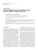
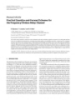
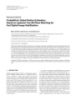
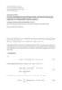
- 2 EURASIP Journal on Advances in Signal Processing We study the benefits of CPS-PC on the downlink of receiver algorithms. In general, the feasibility of interference a cellular network with correlated receive antennas, and alignment over a limited number of signaling dimensions is make a few key contributions. First, a criterion to quantify still an open problem. the performance improvement for cell boundary UEs, while The multiple antennas employed in a MIMO system controlling the loss in performance of cochannel in-cell UEs, increase the available degrees of freedom, which can be is developed based on received SINR. Second, the benefits of used for interference suppression [13, 14]. Cooperative power sharing across antennas based on minimal feedback MIMO techniques involving coordinated transmissions by about the link characteristics is illustrated by taking the adjacent cell-site BS antennas is seen as a promising approach case of a BS with two transmit antennas. Third, a simple for improving the SINR of cell-boundary users. Capacity and effective CPS-PC scheme is proposed alongside a user analyses, under different sets of assumptions [15–19], show grouping framework, which ensures that a cell-boundary promise. In one framework, where all the BS transmission UE in one cell shares spectral resources only with in-cell points are connected to a central processing unit (centralized UEs in neighboring cells, and which makes the algorithm multiuser MIMO precoding), and can perform coherent for precoder selection causal. A distributed algorithm for transmission based on channel state information (CSI) and cooperation among BSs with per-antenna power control, the user data, interference can be almost fully eliminated which allows cochannel BSs to minimize their contribution [17–21]. However, considering the complexity involved and of interference to the cell-boundary UEs is given. Finally, the large-scale coordination that needs to happen across simulation-based performance evaluation of the proposed the network, this looks as a distant reality. This will scheme in terms of cell-edge (5% point in the CDF) and necessitate a fundamental change in the way base stations are average spectral efficiency is provided using a multicell implemented. simulator, for a system with two antennas each at the BS and Since each BS can be viewed as trying to maximize the UE, respectively, following the methodologies in the 3GPP utility to the UE it is serving, this problem can also be LTE standard [3]. characterized using Game Theory [22–30]. Early studies on The paper is divided into sections discussing prior art, SIR balancing using convex and nonconvex optimization system model description, antenna power sharing frame- methods are available in [22–24]. From a game-theoretic work, the proposed CPS-PC scheme, simulation results and perspective, interference avoidance and iterative water-filling conclusions. Throughout the paper, lower-case letters are algorithms lead to a stable operating point termed as used for scalars, boldface lower-case letters for vectors, and the Nash equilibrium. However, these points often turn boldface upper-case letters for matrices. The ith element of out to be suboptimal from a network perspective and indicate inefficiency in wireless network operation [26, 27]. A the vector a is denoted by a(i) , the ith column of matrix A is denoted by A(i) , the ( j , i)th element of matrix A is denoted solution consisting of a linear combination of beamforming by a( ji) and the ith element of the set A is denoted by a{i} . vectors and zero-forcing vectors for a MISO interference channel is given in [28]. However, this solution is feasible only when the number of significantly interfered users is less than the number of transmit antennas, thereby making this 2. Prior Art solution infeasible. Moreover, some of these techniques are not applicable when a mix of single and multiple data stream We begin with a brief overview of some of the interference users are present in the system. management techniques [4, 5]. A simple coordinated means for interference management is spectrum reuse which can be, for example, 1 : 1 (reuse in every cell) or 1 : 3 (reuse in 3. System Model and Precoding every third cell). Here the cell capacity is traded to improve Weight Computation the throughput of low-SINR UEs. An enhancement to this approach is fractional frequency reuse (FFR) [4], where We consider the downlink of an OFDMA-based cellular the reuse can be between 1 : 1 and 1 : 3. Advanced MIMO network having K cell sites (as in Figure 1, showing 9 techniques and wideband communication schemes allow for cell sites). Every UEk employs Nk antennas and each BSk techniques to handle interference without sacrificing effec- employs Mk antennas. Each BS serves its active UEs using tive spectrum utilization. This makes FFR a less preferred orthogonal time-frequency resources, and every BS reuses choice. all the resources. Since OFDM modulation transforms Interference management schemes such as interference the frequency selective channel into multiple flat fading avoidance and iterative water filling, which treat interference channels, we assume in our analysis that the signal in each as noise, and where each transmitter acts selfishly to align resource undergoes a flat-fading channel over its bandwidth. its transmissions along those directions where its desired A more realistic frequency selectiveness within a resource is receiver experiences the least interference [6–8], are well introduced in the simulations by employing an appropriate known. Interference management can also be studied as a channel model. The (b, a)th channel coefficients for the links vector signal processing problem, where the interfering BSs Hk j (Nk × M j ) between BS j and UEk at any given instant based on global channel knowledge can coordinate their (√ are given by h(ba) = zkba) cr − p 10S/10 . Here r denotes the link transmissions such that the interfering signals get aligned kj j distance between the transmit and receive antenna arrays, p and appear as if they are originating from a single source [9– the path loss exponent and c is the median (over shadow 12]. This enables interference cancelation with appropriate
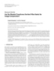
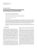
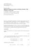
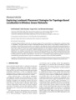
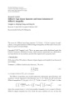
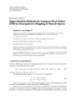
- EURASIP Journal on Advances in Signal Processing 3 500 Eigen spread (λmax /λmin ) 400 8 7 300 9 3 2 6 200 100 1 0 0 0.2 0.4 0.6 0.8 1 Correlation coefficient (ρ) 4 5 Figure 2: CDF of Spectral Efficiency when Basestations employ two antennas each. Figure 1: Cellular system showing in-cell and cell-edge users in an interference channel setup. transmit on a common resource a single stream of forward- error-correction-(FEC-) coded blocks sk to the respective UEs, chosen from a PSK or QAM alphabet set, employing multiple antennas for beamforming. The vector ek (Nk × 1) fading) of the multipath-averaged path gain at a reference distance (r = r0 ). S ∼ N (0, σS ), making 10S/10 a log-normal 2 corresponds to the background noise at UEk of variance σ 2 , shadow fading random variable, and zkba) ∼ CN (0, 1) ( modeled as a circularly symmetric additive white Gaussian j random variable. The background noise is a superposition of represents multipath fading. The random variables zkba) will ( j the residual interference in the system and thermal noise. The be uncorrelated in the absence of transmit and receive array transmit power at BSk is given by E[ xk 2 ] = Pk . We assume correlation. Since a system with two antennas at the BS and normalized unity transmit power (Pk = 1) and make use at the UE is widely considered as a practical configuration, † of precoders of the form vk vk = 1. This type of precoding, we limit our discussions to this use case. often termed as unitary precoding, is known to be more The antennas at the receiver are highly correlated due to robust to channel quantization and variations [32]. Sk is the presence of correlated scatterers near the terminal, due to the index set of the dominant interferers to UEk . With new- their proximity and due to UE size limitations. Correlation generation network deployment tools such as cell planning, amongst antenna elements can be mathematically modeled antenna mast height and radiated power optimization, using a rotation matrix R [31]. For a system with two receive sectored antennas, horizontal and vertical antenna tilts, and 1ρ antennas, this is given by ρ∗ 1 , where ρ characterizes a homogenous propagation environment, it can be ensured the degree of correlation between the array elements. The that the base stations neighboring a given sector will with equivalent channel matrix can now be given as Gk j = R Hk j . high probability be the ones causing most of the interference Correlation destroys the richness of the channel, which can to it [33]. In this work, we assume that indeed this is the case, be characterized typically using the degree of correlation, and refer to these interferers as dominant, meaning, their captured by the parameter κ = λmax /λmin , defined as the removal from the system results in the UE’s performance ratio of the largest to the smallest eigenvalues of G. Figure 2 appearing to be only noise-limited (which includes residual compares κ for the 2 × 2 correlated MIMO channel G, interference). Based on system simulation studies performed for ρ ranging between 0 and 1. It can be seen that the along the lines of [33], the value for |Sk | is typically 0 for an value of κ starts shooting up as the value of ρ exceeds in-cell UE, and 1 (at sector edges) or 2 (at the cell edges), 0.7. This condition happens when λmin starts approaching and rarely 3 or more (due to nonhomogenous propagation zero. Eventually as ρ approaches 1, the MIMO system starts conditions). It is assumed that the channel parameters Gk j in behaving like a typical MISO system. In our work, we assume (1) can be estimated well for all dominant interferers from strong receive-side correlation with ρ = 0.9. their respective reference signals (pilots). In this work |Sk | is Now the matched-filtered, symbol-sampled, complex assumed to be a predetermined value. If, for example, |Sk | is baseband data received by UEk on the given resource for a assumed to be 2 for all UEs, then strongest two interfering single channel use can be given as BSs for each UE are modeled using channel parameters, while the remaining interferers are clubbed with the thermal ∀k ∈ K , yk = Gkk vk sk + Gk j v j s j + ek , noise and modeled as a Gaussian. It is assumed that the (1) j ∈Sk channel parameters can be estimated for these two interferers in all cases. where K {1, 2, . . . , K } is the index set of the K users scheduled to use the same time-frequency resource at the different cell sites. Here yk (size Nk × 1) is the received signal 3.1. Performance Measure. The equalized output of the † vector and vk (Mk × 1) the preprocessing vector. The BSs each receiver is given by sk = wk yk , where wk is a Nk × 1 vector.
- 4 EURASIP Journal on Advances in Signal Processing The effective SINR (γk ) is the key parameter for designing the of a codebook for closed-loop based precoding has been beamforming precoders, since the rate (Rk = log(1 + γk )) an extensive topic of research [34]. In the interest of simplicity, we assume the precoding vectors vkd) of the form ( and BER can be expressed in terms of it. For a given set of precoders V , γk experienced by UEk with a maximal ratio T [1 e jθa ] , (0 ≤ θa ≤ 2π ) for the 2 transmit-antenna combiner (MRC) at the receiver is given as, case. Such precoders change only the phase of transmission and hence are preferred due to their constant modulus 2 Gkk vk γk = . (2) property. Equation (1) can now be appropriately modified 2 + σ2 Gk j v j j ∈Sk and rewritten for the case when Nr = 1 as follows: The Effective SINR Is Given by the Ratio of the Signal Power (11) (12) (11) (12) yk = gkk + e jθk gkk sk + gk j + e jθ j gk j s j + ek . to the Sum of the Interference Powers Leaked into UEk and the j ∈Sk Residual Noise. It is evident that the SINR after equalization (3) is only a function of the signals (Gk j v j ) leaked from the different BSs. Note that UEk can estimate Gk j v j through The equalized SINR (γk(b) ) of UEk can then be given as, training sequences. From (2), we observe that γk of UEk 2 (11) (12) gkk + e jθk gkk depends not only on its own beamforming vector vk , but γk ( b ) = . (4) 2 also on the beamforming vectors of all other cochannel UE j ’s (11) (12) gk j + e jθ j gk j + σ2 j ∈Sk (v j , j = k). This makes individual optimization of every γk / quite difficult. It can be observed from (4) that the maximum value for (11) (12)† γk(b) occurs when θk = − gkk gkk (beamforming angle) High-SINR User. With conventional single-cell beamform- (11) (12)† and θ j = π − gk j gk j ing, v j is chosen as a function of the link G j j seen between (beam canceling angle). This BS j and UE j , to maximize the desired signal strength. condition can be approximated as closely as desired by Assuming a codebook V = {V1 , V2 , . . . , V|V | } consisting employing a sufficiently large codebook. It may be noted that of |V | code vectors, we define for v{a} ∈ V , Lk j (v{a} ) = this maximum value can be obtained only when multiuser Gk j v{a} 2 , as the signal strength leaked from BS j into UEk . scheduling across cells [35] is employed. We assume that When the objective at the transmitter is to maximize signal the cell-boundary UE feeds back information for its best B strength at the receiver, then BS j chooses v j = v{a} which resources, in terms of data rate, each separated by at least one maximizes G j j v j 2 . This increases the numerator of (2). coherence-band (to ensure the channels are uncorrelated) It may be noted that this is a good choice for a in-cell and that there are U high-SINR users in the system, user, as in this case residual interference dominates (i.e., contending for scheduling in these bands. As the value of 2 ≤ σ 2 ). This is also the optimal choice in the l∈S j G jl vl BU → ∞, it will be possible to identify at least one resource absence of any cooperation among the different BSs. and a corresponding in-cell UE, which has the same precoder request as the cell-boundary UE, thereby ensuring that the Low-SINR User. For a user at the cell boundary intercell gain in (4) can be achieved with a probability of one. interference is far above the residual interference in the system (i.e., j ∈Sk Gk j v j 2 > σ 2 ). This is a situation where 3.2. Power Control with Cooperation. With high receive cooperation among the different base stations will help. If the antenna correlation, gains from receive diversity, spatial only objective of BS j , j ∈ Sk , is to minimize the interference multiplexing or interference rejection are not realizable. caused to UEk , then BS j would choose v j = v{a} which However, the multiple antennas can still be used to steer the minimizes Gk j v j 2 . However, this can be deleterious for signal power in the desired direction. In this subsection, we its own user UE j . A preferred choice for v j = v{a} is one consider how side information about the relative channel which will minimize interference at UEk while still ensuring strengths of the two transmit antennas can be used for acceptable performance for UE j . With cooperation, BS j , j ∈ achieving additional performance gains. Let α2 and 1 − α2 Sk , chooses a compromise precoder v j , thereby reducing the correspond to the fixed relative power levels employed at the value in the denominator of (2) to the extent it can afford, two antennas (keeping the total transmit power constant). without sacrificing the performance of its own in-cell UE. We assume that α2 > 1/ 2 without loss of generality. Feeding BSk selects vk to maximize the value in the numerator. An back information about the relative channel strengths as algorithm for such precoder-based cooperation is explained seen from the receiver will need one bit (e.g., indicating in Section 4. which among the two antennas should employ power level α2 ). The effective precoding vector can thus be given as √ Observation 1. When the user data and CSI are available at a T T [α 1 − α2 ] [1 e jθ ] , where is the element wise product central processing unit, as in the case of centralized multiuser operator. Equation (3) can now be appropriately modified MIMO precoding, it is possible to design precoders, thereby and rewritten as follows: creating directional beams towards the desired user, and nulls (11) (12) yk = αgkk + 1 − α2 e jθk gkk sk in the direction of the interfered user. But with distributed cooperative precoding, one can only design precoders which (5) (11) (12) can maximize signal strength and minimize interference αgk j + 1 − α2 e jθ j gk j s j + ek . + leaked in the direction of the interfered user.The choice j ∈Sk
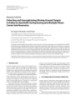
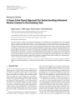
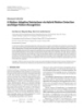
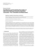
- EURASIP Journal on Advances in Signal Processing 5 (11) (12)† Define ϑk j = θ j − gk j gk j as the angular offset with respect 12 10 to the beamforming angle. The equalized SINR (γk( p) ) of UEk can now be given as 8 √ 6 Array gain/loss (dB) 2 (11) (12) α gkk + 1 − α2 cos(ϑkk ) gkk 4 γk ( p ) = . √ 2 (11) (12) α gk j + 1 − α2 cos(ϑk j ) gk j + σ2 2 j ∈Sk (6) 0 −2 Let φ ( used to represent either of variables i, j or k) −4 denote the convex component (the individual terms in (6)). −6 2 (11) (12) φ = α gk + 1 − α2 cos(ϑk ) gk −8 −200 −150 −100 −50 0 50 100 150 200 (11) 2 (12) 2 Angular offset from beamforming angle (◦ ) (7) 2 2 =α + 1−α gk gk E(Φ): no power control (11) (12) + 2α 1 − α2 cos(ϑk ) gk 1/E(Φ): no power control gk , E(Φ): ideal power control 1/E(Φ): ideal power control where |gk a) | ∼ Ray(0, 1), a ∈ {1, 2} is Rayleigh distributed. (1 E(Φ): one-bit power control When side information on the relative channel strengths 1/E(Φ): one-bit power control across the antennas is not available at the BSs, then the Figure 3: The array gain seen in a 2 Tx ×1 Rx antenna configuration only strategy possible is to transmit through each antenna for varying offset angle with 1 − bit power control. with half the available power. However, when information on the relative channel strength is available, one can use it to increase the value of γk( p) (by altering the individual terms of (6)). control. It can also be observed that power control using a We next evaluate the performance improvement with single bit of information is very useful when the interfering one bit of information about the relative channel strengths, link is made to operate as close as possible to the out-of- for a fixed value of offset angle (ϑk ). Define hu = phase angle. Also observable is the fact that with power (11) (12) (11) (12) max(|gk |, |gk |) and hl = min(|gk |, |gk |). Define control, a part of the array gain lost due to the offset angle pk = {+1, −1} as the parameter characterizing the single can be restored. When the interfering link is operating at the power control bit. Now, α2 is the power level employed on beam canceling angle, single-bit power control yields about hu . Equation (7) can now be rewritten as follows: 3 dB additional gain. φ = α2 h2 + 1 − α2 h2 + 2α 1 − α2 cos(ϑk )hu hl . (8) u l 4. Proposed CPS-PC Algorithm Taking the mean value of (8) and then solving for dE[φ ]/dα = 0 gives the optimum value of α2 . It can A heuristic algorithm for cooperative precoder selection with be shown that hl ∼ Ray(0, 1/ 2) and hu ∼ 2 Ray(0, 1) − power control (CPS-PC) and multiuser scheduling, when (11) (12) BU is not large is explained in this section. We begin by Ray(0, 1/ 2). Moreover, hu hl = |gk ||gk |. Substituting into √ first explaining CPS-PC without multiuser scheduling. The (8) gives E[φ ] = 2α2 + 2π cos(ϑk )α 1 − α2 + 1. Solving for description of the algorithm needs an understanding of the dE[φ ]/dα = 0 gives α2 = (1/ 2)[1 ± 1/ 1 + π 2 cos2 (ϑk )]. manner in which the link behavior changes with the choice We define P = {(1/ 2)[1 + 1/ 1 + π 2 cos2 (ϑk j )], (1/ 2)[1 − of precoder v. As per the algorithm (Algorithm 1), every UEk computes Lk j (v{a} ), v{a} ∈ V for the Gk j link(s) seen from 1/ 1 + π 2 cos2 (ϑk j )], 1/ 2} as the set of possible per-antenna BS j , j ∈ {k} ∪ Sk , based on the reference signals (pilots) power levels employable at the different BS antennas. The used. There is a subset of precoding vectors Vk j of V giving F first two elements in the set correspond to those with one a positive value (in dB scale) for Lk j , which we refer to bit of power control, and the third element corresponds to as cophasing vectors, while the complementary subset Vk j C the case with uniform power across the antennas. It can be seen that p{1} = (1/ 2)[1 + 1/ 1 + π 2 cos2 (ϑkk )] when applied which gives a negative value (in dB scale) are termed as canceling vectors. A vector lk j of the indices in V is created by to hu helps increase the numerator value, and the same when sorting the corresponding Lk j (v{a} ), v{a} ∈ V , in decreasing applied to hl helps to decrease the value in the denominator. (1) Figure 3 captures the array gain (E[φ ]) and array loss order. It may be noted that v{l j j } is the beamforming angle (1/E[φ ]) for varying offset angle. Given for comparison are (|V |) of BS j for UE j and v{lk j } the beam canceling angle of BS j three cases: without power control, with ideal power control (|V |) for UEk . Precoding its transmission using v{lk j } by BS j and with one-bit power control. While the range of angles over which E[φ ] and 1/E[φ ] is positive is 180◦ for the can potentially result in severe performance degradation for UE j . With cooperative precoding, however, BS j , j ∈ Sk nonpower-controlled case, the same exceeds 200◦ with power
- 6 EURASIP Journal on Advances in Signal Processing for all i such that i ∈ K do (1) UEi identifies BS j , j ∈ Si (2) UEi estimates Gi j , j ∈ {i} ∪ Si {link quality estimate} (3) UEi computes li j , j ∈ {i} ∪ Si {sorted precoder index} (4) UEi computes pi j , j ∈ {i} ∪ Si {power control choice} (5) UEi forwards the pi j s and li j s to BSi {feedback on-air} (6) (7) end for BSi retains lii , pii and forwards li j , pi j , j ∈ Si to BS j {feedback over back-haul} (8) (1) BSk serving {cell-edge}UEk chooses v{lkk } , pkk for precoding transmission to UEk (9) BS j , j ∈ Sk arrives at v for {precoding transmission to in-cell}UE j as follows {l o } (10) for c = |V | to |V / 2| do {least to minimal leakage} (11) for f = 1 to |V / 2| do {best to minimal array gain} (12) (f) if l j j = l(cj) then (13) k lo ← l(cj) {optimal value} (14) k (15) goto step (19) (16) end if (17) end for (18) end for if p j j = pk j then (19) BS j , j ∈ Sk employs po = p j j ∈ {p{1} , p{2} } {power control employed} (20) (21) else BS j , j ∈ Sk employs po = {p{3} } {uniform power employed} (22) (22) end if Algorithm 1: The CPS-PC algorithm without multiuser scheduling. chooses a compromise precoder v{lo } which is in the set V Fj ∩ j cell 3 Vk j . This choice of precoder can considerably minimize the C p interference contributed to UEk , while restricting the loss in array gain for UE j . In the rare case when V Fj ∩ Vk j = C j (|V |/ 2) φ (empty set), BS j picks v{lk j } , which also exists in V Fj j cell 2 (because V Fj + V Cj = V ). p j j Similarly, when the power level requested by the cell- boundary UE is the same as the value requested by the in-cell UE ( p j j = pk j ), then BS j employs power level po (either p{1} or p{2} ) on the first antenna, defined by p j j . When p j j = pk j , / cell 1 p then BS j employs p{3} on both its antennas. The different UEi , i ∈ K make the necessary measurements and then forward the quantized values (li and pi ) to the serving W1 W1 W1 BSi . The information (li j and pi j ) needed for cooperation is then forwarded to the relevant cochannel BS j , j ∈ Si via Figure 4: Spectrum sharing framework illustrated: the shaded part the backhaul communication links. BS j then cooperates, also of the spectrum is used by cell edge users. taking into account the feedback received from UE j . 4.1. Causality of the CPS-PC Algorithm. In a general coop- edge subband). The remaining UEs are scheduled in the erative precoding setup, the choice of precoder made by a remaining subbands (in-cell subband). In this framework, it is implicitly assumed that |Sk | = 2. While this type of given BS depends on the choices made by the other BSs in the cochannel set. This leads to violation of causality grouping is reminiscent of FFR [4], the spectral reuse here in precoder selection, unless the base stations employ a remains unity. Stated simply, this is a scheduling of UEs in the different cells, which ensures that a low-SINR UE gets centralized algorithm for coordination. To overcome this problem, we employ a user grouping framework as in Figure interference only from BSs serving in-cell UEs on the same 4, whereby adjacent cell sites do not allot the same spectral resource, which themselves do not require cooperation. In resources simultaneously to users at the cell boundaries. In this setup it is the low-SINR, cell-boundary UE that requests this framework, the entire frequency band is divided into cooperation from the interfering BSs. Each base station BS j , j ∈ Sk serving in-cell UE j each choose a compromise three (logical) subbands and the low-SINR UEs are assigned a different third of the band by neighboring cell-sites (cell- precoder, based on the feedback from its own UE j , and from
- EURASIP Journal on Advances in Signal Processing 7 precoder request as the cell-boundary UE of an adjacent Table 1: Gain and loss of CPS-PC. sector, or a corresponding compromise can be shown to be, BU CPS gain (dB) Avg. in-cell loss (dB) 1 1.90 0.56 Pr lo = lkij} { 2 3.65 0.27 ⎧ 4 4.91 0.12 ⎪ BU ⎪ ⎪1 − 1 for i = |V |, ⎪ , ⎪ ⎪ ⎪ 2 ⎪ ⎪ ⎪ ⎪ ⎪ ⎪ ⎪ i − |V |/ 2 B U ⎪ ⎪ ⎪ UEk . In contrast, BSk employs the optimal precoding vector ⎪ 1− ⎪ ⎪ i − |V |/ 2 + 1 ⎪ ⎪ for beamforming to UEk . The actions of BSk are not of much ⎪ ⎪ ⎨ consequence to UE j , j ∈ Sk , since these are high-SINR UEs i − |V |/ 2 + 1 B U |V | = ⎪ to which BSk does not generate much interference. Thus, the for |V | > i > × ⎪ , , ⎪ ⎪ |V | ⎪ 2 ⎪ distributed precoder selection at all BSs is rendered causal. ⎪ ⎪ ⎪ ⎪ ⎪ ⎪ 1 BU |V | ⎪ ⎪ ⎪ for i = ⎪ , , ⎪ |V | ⎪ 4.2. CPS-PC in Practice with Multiuser Scheduling. We dis- 2 ⎪ ⎪ ⎪ ⎪ cussed in Section 3.1 that multiuser scheduling can mitigate ⎪ ⎪ ⎩0 else where. the loss in performance of the in-cell UE due to cooperation asymptotically as BU → ∞. In Section 4, we discussed (9) Algorithm 1, which implements a compromise precoder This probability is seen to be a function of the product selection without multiuser scheduling that minimizes the BU . For the case when Nk = 1, Mk = 2 and |Sk | = 2, for loss in performance for the in-cell UE. While such coop- all k, the array gain and loss for some typical values of BU eration helps in improving the performance of the cell- are given in Table 1. We can see that as BU approaches even boundary UE, the performance of the in-cell UE would modest values such as 4, the loss incurred by the in-cell UE normally degrade because of the compromise precoder becomes negligible. Similarly, the choice of the power control selected by its serving BS. However, in wide-band systems parameters can be shown to have the following distribution, employing OFDM-based multiple access, one can employ user scheduling to make effective use of the multiuser Pr po = p{i} diversity in the system and minimize the performance degradation. One simple, yet very useful, approach is for ⎧ ⎪1 BU the scheduler to pair wherever possible a high-SINR UE, 1 ⎪ ⎪ ⎪2 1 − for i ∈ {1, 2} when p j j = pk j , ⎪ , ⎨ which happens to have the same precoder choice as the one 2 = requested by the cell-boundary UEk of the neighboring cell. ⎪ ⎪ ⎪1 BU ⎪ We now consider CPS-PC with multiuser scheduling and ⎪ ⎩ for i = 3 when p j j = pk j . , / modest values for B and U , in order to overcome the loss 2 (10) in performance of in-cell UEs. When multiuser scheduling is combined with the CPS- We have illustrated using system performance metrics in PC scheme, every BS schedules its own cell-boundary UEs Section 5 that this cooperation strategy when combined with in the cell-edge subbands based on the rates requested multiuser scheduling is indeed beneficial for both in-cell by them on each of the resource contended by them in and cell-edge users. Note that this approach to cooperation these subbands. Typically, UEs requesting the highest rates requires knowledge of lk j and pk j corresponding to links are scheduled in those resources, which is also what we gk j of (cell-boundary) UEk at BS j . This requires a modest have adopted in our simulations. Once the cell-boundary UEs get scheduled, the corresponding precoder requests amount of back-haul capacity between BSs, apart from the are shared with the interfering BSs. Based on the precoder on-air feedback from UEk to BSk . This type of feedback requests received and such precoder requests from UEs complements the link-adaptation-related feedback present associated with it, the BSs schedule the in-cell UEs on the in existing cellular systems. The UEs also need to know the choice made for v{lo } in order to equalize correctly. in-cell subbands. This is done on a resource-by-resource basis. The BS tries to identify the UEs matching the same This can be either ensured through explicit feed-forward precoder requested by the cell-boundary UE, amongst those transmission, or by transmitting precoded pilots to facilitate contenting for that resource. In case there is a match, the estimation by UE j of the combined channel G j j v j . CSI UE having the highest rate amongst them is scheduled. In acquisition and feedback between BSs is the price to be the case when there is no match, the BS adds a rate offset paid in order to achieve the true gains of such cooperation to all those UEs contending, corresponding to a statistical strategies. Given the complexity of network deployments and measure of the offset angle given by their respective lk j s, the sensitivity of this feedback information to delays and and then schedules the UE with the given offset and serves errors, it is necessary that the feedback rate be kept low, but with a correspondingly reduced rate. This continues, until made available via low-latency links. a UE is identified to be scheduled on that resource. The In summary, the CPS-PC scheme proposed in this paper, probability of identifying an in-cell UE having the same employs a simple distributed algorithm for cooperation.
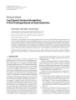
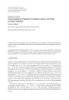
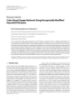
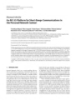
- 8 EURASIP Journal on Advances in Signal Processing With a modest amount of CSI exchange amongst adjacent 2 cell BSs, this scheme enables the BSs to decide on a precoder 1.8 that will minimize the signal strength leaked into adjacent sectors. The user grouping framework ensures that the 1.6 precoder selection amongst cooperating BSs remain causal. Rate (bpcu) It also ensures that interference-limited UEs benefit from 1.4 a minimized interference leakage from adjacent cells. The number of dominant interferers is assumed to be two. 1.2 However, this number can be extended to handle more interferers, provided the user grouping framework is appro- 1 priately modified. Multiuser diversity scheduling ensures 0.8 that the choice of precoder desired by the cell-edge UE can be ensured without compromising on the link performance of a cooperating BS to its own UE. Since the proposed scheme 0 5 10 15 assumes the existing network infrastructure in its design, SNR (dB) there is no need for any framework change for adoption into Cooperation + power control emerging broadband wireless systems. Cooperation Zero forcing Nash equilibrium 5. Performance Results Figure 5: Average rates for the different transmission schemes with In this section, we present simulation results for the proposed 2-antennas at the basestation for varying average SNRs (all channels CPS-PC scheme. In the first part of this section, we com- are i.i.d. Rayleigh fading). pare, using link-level simulations, the proposed cooperation scheme with the MISO interference channel solutions in [27] and conventional single-cell beamforming. This is followed single-cell precoding is maximized, but nothing is done by numerical evaluation in the 3GPP LTE framework of to mitigate interference. In contrast, zero-forcing by a BS the performance improvement possible with the proposed helps in minimizing much of the interference created to the basestation cooperation scheme in a multicell, multiuser adjacent cell user, without any regard to the performance system, over single cell beamforming. of the link to its own UE. In the proposed cooperation algorithm, we allow the serving BSs to beamform to the cell- 5.1. Link Performance Comparison. Figure 5 compares the edge UEs and the interfering BSs (serving high-SINR UEs average rate achieved, in terms of bits per-channel usage on cochannel resources) to reduce some of the interference (bpcu) for varying signal-to-noise ratio (SNR), of the they cause to the cell boundary UEs. At very high SNR, the proposed CPS-PC scheme with the game-theory based ZF performance approaches the cooperation performance. solutions of zero-forcing and Nash equilibrium [26, 27]. However, in terms of feedback overhead needed, both the Performance comparisons are made for a cell-boundary UE beamforming and cooperation schemes clearly have an edge. experiencing a signal-to-interference ratio (SIR) of 0 dB each from the cochannel transmission of two BSs, employing 5.2. System Performance Evaluation. While the link simula- two antennas each. After including the thermal noise and tions give a perception of how a typical cell-edge UE will residual interference, the effective SINR is well below −3 dB perform, they do not capture the network level gains. To for this interference profile. The user grouping framework gain insight into this behavior we compare the gains of the discussed in Section 4.1 is employed. The constant mod- proposed algorithm over the state-of-art in the 3GPP LTE ulus codebook introduced in Section 3.1 were employed framework. in the simulations. √ The transmit power levels are either √ Pq = {(1/ 2)[1 + 1/ 1 + π 2 / 2], (1/ 2)[1 − 1/ 1 + π 2 / 2]} or Pq = {1/ 2, 1/ 2}. To ensure better averaging of the results, 5.2.1. Models and Assumptions. Some of the simulation snapshot simulations spanning 105 channel realizations were assumptions made regarding the cellular model used are performed. The beamforming-based schemes (cooperation listed in Table 2, which are mostly aligned with the 3GPP with and without power control) employ codebooks of size framework [3]. Identical power is employed for every BS 4 and 8, respectively, whereas in the case of zero-forcing and transmission and the transmit antenna array sends out Nash equilibrium, ideal CSI is assumed to be available at the signals simultaneously from all elements with 41 dBm power. BSs. The averaging is done over 105 channel realizations. The cumulative distribution function (CDF) of the SINR It can be seen from Figure 5 that the proposed cooper- experienced by the users is given in Figure 6. Due to intercell ative precoding algorithms perform better than the game- interference, the SINR seen by a cell-edge user may be as low as −5 dB, compared to a value as high as 20 dB for the in- theoretic solutions. This is due to the fact that the solutions based on game theory are inherently biased in favor of the cell user. The OFDM system model assumed ensures that entity with the highest bargain power (in this case, the in- the cyclic prefix is larger than the longest delay spread in the system. The results are statistically averaged over 104 user cell UEs). At the Nash equilibrium point, the gain from
- EURASIP Journal on Advances in Signal Processing 9 Table 2: Simulation parameters. Traffic models User distribution Uniform Full buffer Data generation Data scheduling Round robin with persistent allocation Radio network models L = 35.3 + 37.6 log(d), d in metres Distance attenuation Shadow fading Log-normal, zero-mean with 8 dB standard deviation Multipath fading 3GPP EPA model [36] Cell layout 19-cell, 3 sectors/cell, hexagonal grid with wraparound Cell radius 1000 metres intersite distance System models Spectrum allocation 10 MHz bandwidth at 2 GHz Doppler 5 Hz Max antenna gain 15 dBi Modulation and coding 3GPP specified [3] Overhead 4 symbols in a subframe of 14 symbols Feedback delay 2 msec 1/ 2 per UE with half-wavelength spacing, ρ = 0.9 UE antennas Network antennas 2 per site with 10-wavelength spacing Users per cell 10, uniformly distributed instantiations. The BSs are assumed to be interconnected via 1 low-latency, low data-rate links. The user grouping scheme illustrated in Figure 4 is 0.8 employed. In each sector, the UEs starting from the lowest SINR are first scheduled in the one-third subband reserved 0.6 for cell-boundary UEs in that sector. Once this subband F (x) is full, the remaining UEs are scheduled in the subband intended for in-cell UEs. Different UEs get serviced with 0.4 different data-rates based on their instantaneous channel conditions. The different power levels employed remain the 0.2 same as that in Section 5.1. The interference is modeled in the system based on the instantaneous SINR experienced by the UE. It is assumed that |Sk | = 2 for all UEs. In the 0 −10 −5 0 5 10 15 20 simulations, the ideal channel parameters are assumed to SINR (dB) be available for all the links. A BS either beamforms on the resource allocated to its cell-boundary user, or cooperates Figure 6: CDF of SINR experienced by a user. for the cochannel neighboring cell-boundary user, while simultaneously serving its in-cell user as best it can by exploiting multiuser diversity. practice, the network will train over the initial few subframes Since the performance improvement with basestation to arrive at the correct modulation and coding level. Since, cooperation is dependent on the quality of CSI information we assume persistent scheduling for the users over tens of estimated by the UEs and fed back to the BSs, a 5% channel subframes, the prediction model can be assumed to be valid estimation error, modeled as zero-mean, complex Gaussian for the entire allocation. The mean and 5th percentile point is assumed and added to the ideal channel parameters. A of spectral efficiency are used as the metrics for average and single transmission per coded block, matched to the channel cell-edge performance, respectively, which provide useful conditions is considered, and hybrid-ARQ is modeled as in insight into system behavior. [37]. Based on the precoder chosen, the channel realization and the active interferer set, a SINR is calculated for each link assuming a MMSE receiver model at 10% block-error 5.2.2. Numerical Results. Simulation results are presented rate, and then an effective SNR is calculated per downlink for the two cases where the UEs employ 1 and 2 antennas, resource block (the time-frequency resource allocated to an respectively. We have used a codebook with four precoding vectors (i.e., |V | = 4 and θx = n(π/ 2), n ∈ {0, . . . , 3}). user). This SNR is mapped to active radio-link data rates for each active user using the EESM prediction model [38]. In In conventional beamforming, the UEs feed back 2 bits to
- 10 EURASIP Journal on Advances in Signal Processing 1 1 0.9 0.9 0.8 0.8 0.7 0.7 2 1 CDF of user CDF of user 0.6 0.6 4 0.5 0.5 3 0.4 0.4 0.3 0.3 0.2 0.2 0.1 0.1 0 0 0 0.5 1 1.5 2 2.5 3 3.5 4 0 0.5 1 1.5 2 2.5 3 3.5 4 Spectral efficiency (bps/Hz/cell) Spectral efficiency (bps/Hz/cell) Single-cell beamforming 1. Single-cell beamforming, ρ = 0.9 Cooperation without power control 2. Cooperation without power control, ρ = 0.9 3. Cooperation with power control, ρ = 0.9 Cooperation with power control 4. Single-cell beamforming, ρ = 0 Figure 7: CDF of Spectral Efficiency when UEs employ one antenna each. Figure 8: CDF of Spectral Efficiency with ρ = 0.9 and UEs employing two antenna each. the serving BS for each of the B = (5) resources. There processing to mitigate some interference for cell-edge UEs. The mean SE of conventional beamforming for ρ = 0 is a natural ordering of precoding vectors with respect to Lk j (v{a} ). With cooperation, the in-cell UEs feed back and ρ = 0.9 are 1.94 and 1.40 bps/Hz/cell, respectively, and the 5th percentile values are 0.45 and 0.08 bps/Hz/cell, 2 bits for the optimal precoding vector and 1 additional respectively. The correlation takes away about 28% of the bit to indicate the direction in which one should move mean SE gains and the 5th percentile value falls by about in the naturally-ordered codebook, when the BS seeks to 82%. With ρ = 0.9, mean SE value increases to 1.76 cooperate. With power control, one more additional bit will and 1.91 with and without power control, whereas the 5th be employed to indicate which of the two antennas should percentile value increases to 0.26 and 0.32, respectively. This transmit with the higher transmit power. A cell-edge UE corresponds to a 26% and 37% improvement in the mean SE will thus feed back 3 bits (2 + 1) to its serving BS and 4 and 225% and 300% for the 5th percentile value, respectively. bits (2 + 1 + 1) for every cooperating BS, for each of the B While the improvements seem to be very high, it may be resources. noted that 0.32 bps/Hz/cell/user is in itself a modest value in In Figure 7, the SE comparisons are made for the single absolute terms. receive-antenna case. Conventional single-cell beamforming is compared against cooperation, with and without power control. The mean SE for the three different schemes are 1.38, 6. Conclusions 1.60, and 1.77 bps/Hz/cell and the 5th percentile values are 0.13, 0.23, and 0.28 bps/Hz/cell, respectively. Cooperation In this paper, we have investigated a Cooperative Pre- helps to improve the fifth percentile point and mean spectral- coder Selection with Power Control (CPS-PC) scheme efficiency values by 77% and 16%, respectively. With power for enhancing the performance of severely interference- control, the corresponding improvement values are about limited cell-boundary users. The problem was studied in 115% and 28%, respectively. There is a significant improve- the framework of an interference channel, the capacity of ment in performance of the proposed cooperation scheme which still remains an open problem. A novel algorithm for when power control is employed. It may be noted that the distributed base station cooperation was proposed and the gains accrue because of both cooperation and multiuser performance of this algorithm was illustrated in a practically scheduling. While cooperation ensures that the performance realizable framework. A realistic system configuration with of the cell-boundary, low-SINR user improves, the in-cell two antennas at the basestation and two at the user terminal user’s performance (in the form of average throughput) does was employed in the analysis. An analytical expression for not degrade because of multiuser scheduling. employing power control across the transmit antennas was given. The criterion to be adopted by the different BSs when In Figure 8, the SE comparisons are made for the two- receive-antenna case. Conventional single-cell beamforming selecting the precoders while serving in-cell and cell-edge is compared against cooperation, with and without power users was discussed. We demonstrated through simulations control for a correlation coefficient ρ = 0.9. To illustrate that systems with severe receive-side antenna correlation are how much rate is lost because of correlation, the single- a use case for the proposed solution. Link level analysis cell beamforming scheme is also compared with a value showed that the proposed cooperation schemes give signif- for ρ = 0. In this case, the receiver can support dual- icant gains over the game-theory based solutions of zero- stream spatial multiplexing when in-cell, and does MMSE forcing and Nash equilibrium. Network-level performance
- EURASIP Journal on Advances in Signal Processing 11 gains characterized in terms of the mean and 5% tail values [9] S. A. Jafar and M. J. Fakhereddin, “Degrees of freedom in the spectral efficiency CDF were also provided. for the MIMO interference channel,” IEEE Transactions on Information Theory, vol. 53, no. 7, pp. 2637–2642, 2007. The precoder-selection based algorithm for base sta- [10] S. Vishwanath and S. A. Jafar, “On the capacity of vector tion cooperation was shown to be useful in improving gaussian interference channels,” in Proceedings of the IEEE the performance of cell-edge users without compromising Information Theory Workshop (ITW ’04), pp. 365–369, Octo- on the mean spectral efficiency. When employing power- ber 2004. control based cooperation, a mean spectral efficiency value [11] V. R. Cadambe and S. A. Jafar, “Interference alignment and improvement of about 28% is reported over conventional degrees of freedom of the K-user interference channel,” IEEE single-cell beamforming for a system with two transmit Transactions on Information Theory, vol. 54, no. 8, pp. 3425– antennas and one receive antenna. For a system where 3441, 2008. user terminals are equipped with two receive antennas, [12] K. Gomadam, V. R. Cadambe, and S. A. Jafar, “Approach- but there is a high correlation factor 0.9 between them, a ing the capacity of wireless networks through distributed mean spectral efficiency gain of 37% is reported. It was interference alignment,” in Proceedings of the IEEE Global Telecommunications Conference (GLOBECOM ’08), pp. 4260– shown that this approaches the performance of single-cell 4265, New Orleans, La, USA, December 2008. beamforming when there is no antenna correlation. The [13] J. G. Andrews, “Interference cancellation for cellular systems: a algorithm employed was shown to be simple, requiring only contemporary overview,” IEEE Wireless Communications, vol. modest overhead when compared with single-cell MIMO 12, no. 2, pp. 19–29, 2005. signalling schemes. Furthermore, the algorithm facilitates [14] H. Dai, A. F. Molisch, and H. V. Poor, “Downlink capacity a causal implementation of distributed precoder selection of interference-limited MIMO systems with joint detection,” for base station cooperation. In contrast to the CPS-PC IEEE Transactions on Wireless Communications, vol. 3, no. 2, scheme, where UEs are scheduled across sectors on the same pp. 442–453, 2004. resource, in multiuser MIMO [39], UEs on the same sector [15] B. L. Ng, J. S. Evans, S. V. Hanly, and D. Aktas, “Distributed with orthogonal precoder requests are scheduled on the same downlink beamforming with cooperative base stations,” IEEE resource. Whereas MU-MIMO improves the cell-capacity Transactions on Information Theory, vol. 54, no. 12, pp. 5491– 5499, 2008. with almost similar cell-edge performance as of single-cell [16] A. B. Carleial, “Outer bounds on the capacity of interference beamforming, the CPS-PC scheme improves the cell-edge channels,” IEEE Transactions on Information Theory, vol. 29, performance without loss in cell-capacity when compared no. 4, pp. 602–606, 1983. to single-cell beamforming. Thus the two schemes employ [17] G. J. Foschini, K. Karakayali, and R. A. Valenzuela, “Coor- MIMO primarily to achieve different ends. dinating multiple antenna cellular networks to achieve enor- mous spectral efficiency,” IEE Proceedings, vol. 153, no. 4, pp. 548–555, 2006. References [18] H. Zhang and H. Dai, “Cochannel interference mitigation and cooperative processing in downlink multicell multiuser [1] E. Dahlman, S. Parkvall, J. Skold, and P. Beming, 3G Evolution: MIMO networks,” EURASIP Journal on Wireless Communica- HSPA and LTE for Mobile Broadband, Academic Press, San tions and Networking, vol. 2004, no. 2, pp. 222–235, 2004. Diego, Calif , USA, 2nd edition, 2008. [19] M. K. Karakayali, G. J. Foschini, R. A. Valenzuelat, and R. [2] S. Sesia, I. Toufik, and M. Baker, LTE—The UMTS Long Term D. Yates, “On the maximum common rate achievable in a Evolution: From Theory to Practice, John Wiley & Sons, New coordinated network,” in Proceedings of the IEEE International York, NY, USA, 2009. Conference on Communications (ICC ’06), vol. 9, pp. 4333– [3] Third Generation Partnership Project (3GPP), “Evolved 4338, Istanbul, Turkey, June 2006. UTRA aspects: Physical Layer Procedures (3GPP TS 36.2xy [20] H. Zhang, N. B. Mehta, A. F. Molisch, J. Zhang, and H. Dai, series documents),” ETSI, 2008. “Asynchronous interference mitigation in cooperative base [4] J. G. Andrews, W. Choi, and R. W. Heath, “Overcoming station systems,” IEEE Transactions on Wireless Communica- interference in spatial multiplexing mimo cellular networks,” tions, vol. 7, no. 1, pp. 155–165, 2008. IEEE Wireless Communications, vol. 14, no. 6, pp. 95–104, [21] M. Sadek, A. Tarighat, and A. H. Sayed, “A leakage-based 2007. precoding scheme for downlink multi-user MIMO channels,” [5] G. Boudreau, J. Panicker, N. Guo, R. Chang, N. Wang, and IEEE Transactions on Wireless Communications, vol. 6, no. 5, S. Vrzic, “Interference coordination and cancellation for 4G pp. 1711–1721, 2007. networks,” IEEE Communications Magazine, vol. 47, no. 4, pp. [22] H. Boche and M. Schubert, “A general theory for SIR 74–81, 2009. balancing,” EURASIP Journal on Wireless Communications and [6] C. Rose, S. Ulukus, and R. D. Yates, “Wireless systems Networking, vol. 2006, Article ID 60681, 18 pages, 2006. and interference avoidance,” IEEE Transactions on Wireless ´ [23] H. Boche and S. Stanczak, “The infeasible SIR region is not a Communications, vol. 1, no. 3, pp. 415–428, 2002. convex set,” in Proceedings of IEEE International Symposium on [7] O. Popescu, C. Rose, and D. C. Popescu, “Signal space Information Theory (ISIT ’05), Adelaide, Australia, September partitioning versus simultaneous water filling for mutually 2005. interfering systems,” in Proceedings of the IEEE Global Telecom- [24] H. Boche and M. Schubert, “Resource allocation in multi- munications Conference (GLOBECOM ’04), pp. 3128–3132, antenna systems—achieving max-min fairness by optimizing December 2004. a sum of inverse SIR,” IEEE Transactions on Signal Processing, [8] S. Ulukus and R. D. Yates, “Iterative construction of optimum vol. 54, no. 6, pp. 1990–1997, 2006. signature sequence sets in synchronous CDMA systems,” IEEE [25] Z. K. M. Ho and D. Gesbert, “Spectrum sharing in multiple- Transactions on Information Theory, vol. 47, no. 5, pp. 1989– antenna channels: a distributed cooperative game theoretic 1998, 2001.
- 12 EURASIP Journal on Advances in Signal Processing approach,” in Proceedings of the IEEE 19th International Sym- posium on Personal, Indoor and Mobile Radio Communications (PIMRC ’08), Cannes, France, September 2008. [26] E. A. Jorswieck and E. G. Larsson, “THE MISO interference channel from a game-theoretic perspective: a combination of selfishness and altruism achieves Pareto optimality,” in Proceedings of the IEEE International Conference on Acoustics, Speech and Signal Processing (ICASSP ’08), pp. 5364–5367, Las Vegas, Nev, USA, April 2008. [27] E. G. Larsson and E. A. Jorswieck, “Competition versus cooperation on the MISO interference channel,” IEEE Journal on Selected Areas in Communications, vol. 26, no. 7, pp. 1059– 1069, 2008. [28] E. A. Jorswieck, E. G. Larsson, and D. Danev, “Complete char- acterization of the pareto boundary for the MISO interference channel,” IEEE Transactions on Signal Processing, vol. 56, no. 10, pp. 5292–5296, 2008. W. Yu, W. Rhee, S. Boyd, and J. M. Cioffi, “Iterative water- [29] filling for Gaussian vector multiple-access channels,” IEEE Transactions on Information Theory, vol. 50, no. 1, pp. 145– 152, 2004. [30] I. Sohn, S. H. Lee, and J. G. Andrews, “A graphical model approach to downlink cooperative MIMO systems,” in Pro- ceedings of the IEEE Global Telecommunications Conference (GLOBECOM ’10), Miami, Fla, USA, December 2010. [31] Third Generation Partnership Project (3GPP), “Physical Layer aspects for evolved UTRA (3GPP TR 25.814),” 3GPP, 1999. [32] D. J. Love and R. W. Heath, “Limited feedback unitary precoding for spatial multiplexing systems,” IEEE Transactions on Information Theory, vol. 51, no. 8, pp. 2967–2976, 2005. [33] WP-5D, “Guidelines for evaluation of radio interface tech- nologies for IMT-advanced,” Tech. Rep. M.2135, 2008. [34] D. J. Love, R. W. Heath, V. K. N. Lau, D. Gesbert, B. D. Rao, and M. Andrews, “An overview of limited feedback in wireless communication systems,” IEEE Journal on Selected Areas in Communications, vol. 26, no. 8, pp. 1341–1365, 2008. [35] W. Choi and J. G. Andrews, “The capacity gain from intercell scheduling in multi-antenna systems,” IEEE Transactions on Wireless Communications, vol. 7, no. 2, pp. 714–725, 2008. [36] Third Generation Partnership Project (3GPP), “Evolved Uni- versal Terrestrial Radio Access (E-UTRA); Base Station (BS) Radio Transmission and Reception (3GPP TR 36.104),” ETSI, 2008. [37] B. Classon, P. Sartori, Y. Blankenship, K. Baum, R. Love, and Y. Sun, “Efficient OFDM-HARQ system evaluation using a recursive EESM link error prediction,” in Proceedings of the IEEE Wireless Communications and Networking Conference (WCNC ’06), pp. 1860–1865, April 2006. [38] K. Brueninghaus, D. Ast´ lyt, T. Salzer et al., “Link performance e models for system level simulations of broadband radio access systems,” in Proceedings of the IEEE 16th International Sym- posium on Personal, Indoor and Mobile Radio Communication (PIMRC ’05), pp. 2306–2311, September 2005. [39] C. B. Ribeiro, K. Hugl, M. Lampinen, and M. Kuusela, “Performance of linear multi-user MIMO precoding in LTE system,” in Proceedings of the 3rd International Symposium on Wireless Pervasive Computing (ISWPC ’08), pp. 410–414, Santorini, Greece, May 2008.
CÓ THỂ BẠN MUỐN DOWNLOAD

-
Báo cáo hóa học: " Research Article On the Throughput Capacity of Large Wireless Ad Hoc Networks Confined to a Region of Fixed Area"
 11 p |
  110
|
110
|  10
10
-
Báo cáo hóa học: "Research Article Are the Wavelet Transforms the Best Filter Banks for Image Compression?"
7 p | 120
| 7
-
Báo cáo hóa học: "Research Article Detecting and Georegistering Moving Ground Targets in Airborne QuickSAR via Keystoning and Multiple-Phase Center Interferometry"
11 p | 116
| 7
-
Báo cáo hóa học: "Research Article Cued Speech Gesture Recognition: A First Prototype Based on Early Reduction"
19 p | 116
| 6
-
Báo cáo hóa học: " Research Article Practical Quantize-and-Forward Schemes for the Frequency Division Relay Channel"
11 p | 114
| 6
-
Báo cáo hóa học: " Research Article Breaking the BOWS Watermarking System: Key Guessing and Sensitivity Attacks"
8 p | 104
| 6
-
Báo cáo hóa học: " Research Article A Fuzzy Color-Based Approach for Understanding Animated Movies Content in the Indexing Task"
17 p | 108
| 6
-
Báo cáo hóa học: " Research Article Some Geometric Properties of Sequence Spaces Involving Lacunary Sequence"
8 p | 94
| 5
-
Báo cáo hóa học: " Research Article Eigenvalue Problems for Systems of Nonlinear Boundary Value Problems on Time Scales"
10 p | 90
| 5
-
Báo cáo hóa học: "Research Article Exploring Landmark Placement Strategies for Topology-Based Localization in Wireless Sensor Networks"
12 p | 118
| 5
-
Báo cáo hóa học: " Research Article A Motion-Adaptive Deinterlacer via Hybrid Motion Detection and Edge-Pattern Recognition"
10 p | 93
| 5
-
Báo cáo hóa học: "Research Article Color-Based Image Retrieval Using Perceptually Modified Hausdorff Distance"
10 p | 97
| 5
-
Báo cáo hóa học: "Research Article Probabilistic Global Motion Estimation Based on Laplacian Two-Bit Plane Matching for Fast Digital Image Stabilization"
10 p | 112
| 4
-
Báo cáo hóa học: " Research Article Hilbert’s Type Linear Operator and Some Extensions of Hilbert’s Inequality"
10 p | 77
| 4
-
Báo cáo hóa học: "Research Article Quantification and Standardized Description of Color Vision Deficiency Caused by"
9 p | 120
| 4
-
Báo cáo hóa học: " Research Article An MC-SS Platform for Short-Range Communications in the Personal Network Context"
12 p | 70
| 4
-
Báo cáo hóa học: "Research Article On the Generalized Favard-Kantorovich and Favard-Durrmeyer Operators in Exponential Function Spaces"
12 p | 102
| 4
-
Báo cáo hóa học: " Research Article Approximation Methods for Common Fixed Points of Mean Nonexpansive Mapping in Banach Spaces"
7 p | 74
| 3


Chịu trách nhiệm nội dung:
Nguyễn Công Hà - Giám đốc Công ty TNHH TÀI LIỆU TRỰC TUYẾN VI NA
LIÊN HỆ
Địa chỉ: P402, 54A Nơ Trang Long, Phường 14, Q.Bình Thạnh, TP.HCM
Hotline: 093 303 0098
Email: support@tailieu.vn
Giấy phép Mạng Xã Hội số: 670/GP-BTTTT cấp ngày 30/11/2015 Copyright © 2022-2032 TaiLieu.VN. All rights reserved.

