


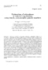
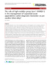
Báo cáo " Using high algebra to design frequency divider include hazard "
lượt xem 3
download
 Download
Vui lòng tải xuống để xem tài liệu đầy đủ
Download
Vui lòng tải xuống để xem tài liệu đầy đủ
Normally the frequency divider designed by Boole algebra and to design a frequency divider with any divide factor, we have to repeat all over again every design step as the same. So to avoid of wasting time and money, instead of using traditional Boole algebra in digital technical we replace it by mathematical models in high algebra. And because of that we can design frequency dividers use computer. 1. Modeling of function circuit
Bình luận(0) Đăng nhập để gửi bình luận!
Nội dung Text: Báo cáo " Using high algebra to design frequency divider include hazard "
- VNU Journal of Science, Mathematics - Physics 24 (2008) 163-170 Using high algebra to design frequency divider include hazard Nguyen Quy Thuong* VNU, 144 Xuan Thuy, Cau Giay, Hanoi, Vietnam Received 8 July 2008; received in revised form 8 August 2008 Abstract. Normally the frequency divider designed by Boole algebra and to design a frequency divider with any divide factor, we have to repeat all over again every design step as the same. So to avoid of wasting time and money, instead of using traditional Boole algebra in digital technical we replace it by mathematical models in high algebra. And because of that we can design frequency dividers use computer. 1. Modeling of function circuit Follow [1,2] show that with one frequency divider has 4/3 factor we need 2 flip flop (FF) and NAND gates to control chain so that with 4 input impulse we just have only 3 output impulse. However using NAND gate to control output impulse likes this, it just right in some cases. So to design frequency divider with any divider K factor (meaning with any input and output impulse follow request of user) we use OR gate to control output impulse. Investigate, for example, the input static D and output static Q of D FF in asynchronous Divider, real binary, 3 input, divide factor K= 7/6) Fig 1. Diagram impulse of frequency divider 7/6. Fig. 2. Frequency divider 7/6 execute follow diagram impulse Fig. 1. ______ * E-mail: thuongnq@vnu.edu.vn 163
- 164 N.Q. Thuong / VNU Journal of Science, Mathematics - Physics 24 (2008) 163-170 From circuit of frequency divider picture 2 and impulse diagram Fig. 1, we realize that in the time of first impulse to sixth impulse have at lease one of three input signal of NAND gate G1 receive 0, so output of G3 {G1,G2} = 1. In this time frequency divider will receive 6 impulses from output gate G4. ˆ To impulse 7 output of gate G2 {Q1, Q2, Q3} receive level 0 and because of that G3 = 0, follow G4 ˆ receive level 0 too. So because of OR gate G2, we controlled output frequency divider is M = 6. From Fig. 2 we have circuit function of frequency divider 7/6 7 K = = Q1Q2Q3 ( Q1 + Q2 + Q3 ) .C (1) ˆ 6 x If frequency divider has K = with any x input impulse, mean any n Flip Flop , example 6 8/6, 9/6, ...x/6 then discover more output Q4, Q5 ….of FF4, FF5… from OR input. Now frequency x divider with K = have circuit function: 6 7 = Q1Q2 Q3 ( Q1 + Q2 + Q3 ) .Q4 Q4 ...C K= (2) ˆ 6 Obvious, because of OR gates then after output impulse position M, circuit will reset. Same as above we have Table 1, x is number of input impulse, M is number output impulse and K is a divider factor. x Table 1. Circuit function of frequency divider with any divide factor K = , x is number of input impulse, M M is number output impulse, here M ∈ [ 4, 31] x K= Function M Q1Q2Q 3 (Q1Q2 + Q3 )Q4 x /4 Q1Q2Q 3 (Q2 + Q 3 )Q4 x /5 Q1Q2Q 3 (Q1 + Q2 + Q3 )Q4 x /6 x /7 Q1Q2Q 3Q4 Q1Q2Q 3Q4 (Q1Q2Q3 + Q4 )Q5 x /8 Q1Q2Q 3Q4 (Q2Q3 + Q 4 )Q5 x /9 x /10 Q1Q2Q 3Q4 [(Q1 + Q2 )Q3 + Q 4 ] 5 Q x /11 Q1Q2Q 3Q4 (Q3 + Q4 )Q5 x /12 Q1Q2Q 3Q4 (Q1Q2 + Q4 )Q5 x /13 Q1Q2Q 3Q4 (Q2 + Q3 + Q 4 )Q5 x /14 Q1Q2Q 3Q4 (Q1 + Q2 + Q3 + Q4 )Q5 x /15 Q1Q2Q 3Q5 x /16 Q1Q2Q 3Q4Q5 (Q1Q2Q3Q4 + Q5 )Q6 x /17 Q1Q2Q 3Q4Q5 (Q2Q3Q4 + Q5 )Q6 x /18 Q1Q2Q 3Q4Q5 [(Q1 + Q2 )Q3Q4 + Q5 ] 6 Q
- 165 N.Q. Thuong / VNU Journal of Science, Mathematics - Physics 24 (2008) 163-170 x /16 Q1Q2Q3Q4Q5 (Q1Q2Q3Q4 + Q5 )Q6 x /17 Q1Q2Q3Q4Q5 (Q2Q3Q4 + Q5 ) 6 Q x /18 Q1Q2Q3Q4Q5 [(Q1 + Q2 )Q3Q4 + Q5 ] 6 Q x /19 Q1Q2Q3Q4Q5 (Q3Q4 + Q5 )Q6 x / 20 Q1Q2Q3Q4Q5 [(Q1Q2 + Q3 )Q4 + Q5 ] 6 Q x / 21 Q1Q2Q3Q4Q5 [(Q2 + Q3 )Q4 + Q5 ] 6 Q x / 22 Q1Q2Q3Q4Q5 [(Q1 + Q2 + Q3 )Q4 + Q5 ]Q6 x / 23 Q1Q2Q3Q4Q5 (Q4 + Q5 )Q6 x / 24 Q1Q2Q3Q4Q5 (Q1Q2Q3Q4 + Q5 ) x / 25 Q1Q2Q3Q4Q5 (Q2Q3 + Q4 + Q5 )Q6 x / 26 Q1Q2Q3Q4Q5 [(Q1 + Q2 )Q3 + Q4 + Q5 ] 6 Q x / 27 Q1Q2Q3Q4Q5 (Q3 + Q4 + Q5 )Q6 x / 28 Q1Q2Q3Q4Q5 (Q1Q2 + Q3 + Q4 + Q5 )Q6 x / 29 Q1Q2Q3Q4Q5 (Q2 + Q3 )Q4 + Q5 )Q6 x / 30 Q1Q2Q3Q4Q5 [(Q1 + Q2 + Q3 + Q4 + Q5 )]Q6 x / 31 Q1Q2Q3Q4Q5Q6 From table 1 and comment above, we realize circuit function of frequency divider with any divider factor have 2 forms: n −1 1 Kn = QQ ...Q .Q = ∏Q ..Q form 1: (3) 1 2 n −1 i n n I =1 A part of function left over in brackets (Table1) is a second form : 2 K n = y + Qn form 2: (4) We need to define function y. 2. Define y of circuit function From circuit function (Table 1) we found the form 2 (Table 2)
- 166 N.Q. Thuong / VNU Journal of Science, Mathematics - Physics 24 (2008) 163-170 x Table 2. Circuit function form 2 apply to frequency divider with divide factor K = , n is number of Flipflop, M F is frequency appear circuit function in proportion to K factor, Fb ∈| 0,1, 2, 3 | is a basic frequency to show circulate of circuit function Flipflop n Basis frequenz FB Frequenz F K = x/M Form 2 +Q 3 Q1Q2 0 0 x/4 + Q3 Q2 1 1 x/5 Q1 + Q2 + Q3 2 2 x/6 1 + Q3 3 3 3 x/7 .Q3 + Q4 Q1Q2 4 0 0 x/8 Q3 + Q4 Q2 1 1 x/9 (Q1 + Q2 ) .Q3 + Q4 2 2 x/10 1 .Q3 + Q4 3 3 x/11 + Q3 + Q4 0 4 x/12 Q1Q2 1 5 x/13 + Q 3 + Q4 Q2 2 6 x/14 Q1 + Q2 + Q 3 + Q4 3 7 x/15 1 + Q3 + Q 4 .Q3Q4 + Q5 Q1Q2 0 0 x/16 .Q3Q4 + Q5 Q2 1 1 x/17 (Q1 + Q2 ) .Q3Q4 + Q5 2 2 x/18 1 .Q3Q4 + Q5 3 3 x/19 (Q1Q2 + Q3 )Q4 + Q5 0 4 x/20 (Q2 + Q3 )Q4 + Q5 1 5 x/21 (Q1 + Q2 + Q3 )Q4 + Q5 2 6 x/22 (1 +Q3 )Q4 + Q5 3 7 x/23 . Q3 + Q 4 + Q5 Q1Q2 0 8 x/24 . Q3 + Q4 + Q5 Q2 5 1 9 x/25 (Q1 + Q2 ) .Q3 + Q4 + Q5 2 10 x/26 1 .Q3 + Q4 + Q5 3 11 x/27 + Q3 + Q4 + Q5 Q1Q2 0 12 x/28 + Q 3 + Q4 + Q5 Q2 1 13 x/29 Q1 + Q2 + Q 3 + Q4 + Q5 2 14 x/30 1 + Q3 + Q 4 + Q5 3 15 x/31
- 167 N.Q. Thuong / VNU Journal of Science, Mathematics - Physics 24 (2008) 163-170 From table 2 we realize: circuit function need to find matching with each divide K factor depend on n and F, also we can build the relationship between n, F, M M = 4.2n-3 + F (5) F = M - 4.2n-3 (6) Provide: - n is a number of Flipflop take parts of divider. - F is frequency appear of circuit function in each frequency divider n- FF, follow one circulate from 0 to 2n - 1 Also from table 2 we realize a part of circuit function of frequency divider having output impulse M from 4 to 7 (in proportion to n = 3, F = (0, 1, 2, 3)) is just a part of circuit function have output impulse M ≥ 8 ( this is Q1Q2 ; Q2 ; Q1 + Q2 ; 1). So we take this circuit function make a basic form and symbol as yn=3 to define circuit function of all other frequency divider: [ ] A if F = 0, 2 n −2 − 1 y n =3 ( A1 , A2 ) = 1 (7) [ ] A2 if F = 2 n −2 , 2 n −1 − 1 In which: 0 if F = 0 with ξ = A1 = (Q1 +ξ) . Q2 (8) n −2 1 if F = 2 − 1 It call Product Form n− 2 0 if F = 2 with ξ = A2 = (Q1 +ξ) + Q2 (9) 1 if F = 2 n−1 − 1 It call Sum Form From (8) and (9) and consider Q1 +ξ = Aξ we have: y n =3 = (Q2 + β ) Aξ + β Q2 (10) In which: [ ] 0 if F = 0, 2 n −2 − 1 β = (11) [ ] 1 if F = 2 n− 2 , 2 n −1 − 1 2 K n =3 = y n =3 + Q3 Thus: (12) From table 2 show that circuit function in proportion to n = 4, when Frequency F b = (0,…3) = [0, ..., 2n-2 -1] then circuit function has also product form and sum form as yn=3 a nd this circuit function include circuit function of yn=3. We call this circuit function form is yn=4 y n =4 = (Q3 + ψ ) y n=3 + ψQ3 Thus (13) [ ] 0 if F = 0, 2 n− 2 − 1 ψ = In which: (14) [ ] 1 if F = 2 n −2 , 2 n−1 − 1 K n2=4 = y n= 4 + Q4 Thus: (15) n-2 n-2 Same as let n = 5 with Fb= (0,...7) = [0, ..., 2 -1] and n = 6 with Fb= (0,...15) = [0, ..., 2 -1] Thus: y n =5 = (Q4 + λ ) y n= 4 + λQ4 (16) [ ] n− 2 0 if F = 0, 2 − 1 λ = with: (17) [ ] 1 if F = 2 n− 2 , 2 n−1 − 1
- 168 N.Q. Thuong / VNU Journal of Science, Mathematics - Physics 24 (2008) 163-170 K n2=5 = y n =5 + Q5 Thus: (18) y n =6 = (Q5 + θ ) y n=5 + θQ5 and: (19) [ ] n− 2 0 if F = 0, 2 −1 θ = with (20) F = [2 ] 1 if n−2 n −1 −1 ,2 K n2=6 = y n=6 + Q6 (21) 3. The existence of circuit functions follows a certain law From a result above we realize circuit function to n = 6 follow a certain law with repeat periode Fb= [0, 2n-2 -1], a problem now is how to prove with variable intput n > 6 and any value then circuit function follow a certain law when n ≤ 6 or not. Assuming that f ( M ) = K n is a function satisfying term Dirichlet of Fourier [3] theorem on period [0, 2n-2 - 1] = [a,b]. In order to develop f(M) into Fourier series, we form a periodic function g(Fb) having a period either bigger or equal to [b – a] so that [ ] g ( Fb ) = f ( M ) ∀Fb ∈[a, b] = 0, 2 n −2 − 1 ˆ (22) Obviously there are many ways to develop g(Fb) into Fourier series. For each g(Fb) there are corresponding Fourier series, therefore there are a number of Fourier series demonstrating f(M) = Kn , in other words, the circuit function f(M) = Kn with every M is periodicall with period ∆Fb= 2n-2 – 1, in here ∆Fb Determine from table 2. From demonstration above, we realize that circuit function depend on ∆Fb = [0, 2n-2 -1]. With circuit functions in proportion to Fb ∉ [0, 2n-2 -1] then we have to change F to Fb. so to determine of circuit function we need to find the value Fb. From table 2 we have: Fb = F – 4.(n – 3) (23) Now that we can assert that with any variable input n, that is the frenquency divider can (theoretically) divide to infinite number, then the impulse diagram of circuit function change periodically in those periods which have similar impulses, that is circuit functions always have form 1 and 2 according to certain ∆F To here, we define that circuit function of frequency divider is change periodically follow a certain circulate, in other words, circuit function in any form Kn-3, Kn-4 , Kn-5 , Kn-6 , ... have same form apply with same F frequency. From (11) to (18) we can define of 2 comprehensive forms of circuit function of one frequency divider with output impulse and input as we expect: K n2 = (Qn−1 + ϕ ). f n ( y ) + ϕ .Qn −1 + Qn (24) 0 if F = 0, 2n − 2 − 1 ϕ = β ,ψ ,θ , λ = With (25) 1 if F = 2 , 2 − 1 n− 2 n −1 yn = f ( yn −1 ) yn −1 = f ( yn − 2 ) f n ( y) = (26) ... y4 = f ( y3 )
- 169 N.Q. Thuong / VNU Journal of Science, Mathematics - Physics 24 (2008) 163-170 Combine form 1 and 2 we realize that circuit function of frequency divider correspondence with any number of input impulse and number of output impulse expect: 1 2 Kn = Kn + Kn (27) n K n = ∏ Qi [(Qn−1 + ϕ ). f n ( y ) + ϕ .Qn−1 + Qn ].Qn+1 (28) 1 Provide: - n is a number of FF participate in frequency divider - ϕ is show as function (25) - f n ( y ) is show as function (26) - Kn, Kn-1,… K4, K3 are circuit function corresponding to different n 4. Determine hazard of circuit function From circuit function (28) we can see output state Q of Fflipflop in negative (Q ) and not negative Q. Follow [4,5] when have same output in negative form and not negative form then a chance to create hazard is big, so we need to Determinated that circuit stay in one of static – 0 hazard x x (Fig.3a), static-1 hazard x + x (Fig 3b), dynamic hazard x x + x, ( x + x) x ( Fig.3c,d) or not. x + xx xx c) a) x+x (x + x)x b) d) Fig. 3. Basis hazards. From function (28) we can build comprehensive circuit of frequency divider: . . Fig. 4. Comprehensive circuit of frequency divider. From comprehensive circuit we can construct the residual circuit.
- 170 N.Q. Thuong / VNU Journal of Science, Mathematics - Physics 24 (2008) 163-170 Shown in Fig. 5: Fig. 5. The residual circuit of frequency divider. Compare residual circuit of frequency divider (Fig 5) with circuit showing basic hazards (Fig.3), we realize circuits of basic hazards where x and x stay in two different flat surface algorithm and connected series (Fig. 6b). It will appear delay in surface x before come to surface x, this is cause of hazard. On the contrary, with frequency divider x and x also stay in one surface algorithm (Fig. 6a), they are “equal” on another, so it not delay circuit x to appear hazard. In other word, the frequency divider showing in (28) is free hazard. M t ph ng X a) b) Fig. 6. Illustration that frequecy divider is free Hazard. So because of function (28) we design frequency divider with Matlab software without using Boole algebra. From that we can design frequency divider with any divider factor K using computer, and free hazard in circuit function. References [1] G. Scarbata, Synthese und Analyse digitaler Schaltungen, Oldenbourg Verlag Muenchen Wien (2000). [2] Nguyen Quy Thuong, Digital Technics, Vietnam University Publishing House, Hanoi (in Vietnamese), (2008) 575 [3] Nguyen Dinh Tri, Ta Van Dinh, Nguyen Ho Quynh, High Mathematics, Education Publishing House, Hanoi (in Vietnamese), {2004} 415. [4] John Knight, Gliches and Hazard in Digital Circuits, Eletronics Department, Carleton University (2006). [5] Erik Meijer, Hazard Algebra for Asynchronous Circuits, POBox 80.089 NL-3508 TB Utrecht The Netherlands (2006).
CÓ THỂ BẠN MUỐN DOWNLOAD

-

Báo cáo sinh học: "High-resolution quantitative imaging of mammalian and bacterial cells using stable isotope mass spectrometry"
 30 p |
  51
|
51
|  5
5
-

Báo cáo khoa học: "Use of prophylactic fluconazole in a neonatal intensive care unit: efficacy is similar to that described in adult high-risk surgical patients"
1 p | 86
| 5
-

Báo cáo y học: "Pro/con clinical debate: Is high-frequency oscillatory ventilation useful in the management of adult patients with respiratory failure"
3 p | 54
| 5
-

Báo cáo y học: " Injection drug use and patterns of highly active antiretroviral therapy use: an analysis of ALIVE, WIHS, and MACS cohort"
8 p | 41
| 4
-

Báo cáo khoa học: "Should we use central venous saturation to guide management in high-risk surgical patient"
2 p | 51
| 4
-

Báo cáo sinh học: "Electrical protein detection in cell lysates using high-density peptideaptamer microarrays"
11 p | 43
| 4
-

Báo cáo khoa học: "Is it time to increase the frequency of use of high-frequency oscillatory ventilation"
2 p | 42
| 3
-
Báo cáo sinh học: "Estimation of relatedness in natural populations using highly polymorphic genetic"
0 p | 52
| 3
-
Báo cáo y học: "The role of high-mobility group box-1 (HMGB-1) in the management of suspected acute appendicitis: useful diagnostic biomarker or just another blind alley?"
3 p | 45
| 3
-

Báo cáo y học: "Quality evaluation of mycelial Antrodia camphorata using high-performance liquid chromatography (HPLC) coupled with diode array detector and mass spectrometry (DAD-MS)"
6 p | 49
| 3
-

Báo cáo y học: "Marked disability and high use of nonsteroidal antiinflammatory drugs associated with knee osteoarthritis in rural China: a cross-sectional population-based survey"
7 p | 46
| 3
-

Báo cáo khoa học: "Pro-Con Debate: Steroid use in ACTH non-responsive septic shock patients with high baseline cortisol levels"
4 p | 67
| 3
-

Báo cáo toán học: "he relationship between the biochemical control outcomes and the quality of planning of high-dose rate brachytherapy as a boost to external beam radiotherapy for locally and locally advanced prostate cancer using the RTOG-ASTRO Phoenix definition:
8 p | 45
| 3
-

Báo cáo khoa học: " The use of prophylactic fluconazole in immunocompetent high-risk surgical patients: a meta-analysis."
8 p | 46
| 3
-

Báo cáo y học: "Inexperienced clinicians can extract pathoanatomic information from MRI narrative reports with high reproducibility for use in research/quality assurance"
10 p | 54
| 2
-

Báo cáo y học: "Intraoperative fluid optimization using stroke volume variation in high risk surgical patients: results of prospective randomized study"
15 p | 40
| 2
-

Báo cáo khoa học: "High-dose intensity-modulated radiotherapy for prostate cancer using daily fiducial marker-based position verification: acute and late toxicity in 331 patients"
5 p | 68
| 1


Chịu trách nhiệm nội dung:
Nguyễn Công Hà - Giám đốc Công ty TNHH TÀI LIỆU TRỰC TUYẾN VI NA
LIÊN HỆ
Địa chỉ: P402, 54A Nơ Trang Long, Phường 14, Q.Bình Thạnh, TP.HCM
Hotline: 093 303 0098
Email: support@tailieu.vn
Giấy phép Mạng Xã Hội số: 670/GP-BTTTT cấp ngày 30/11/2015 Copyright © 2022-2032 TaiLieu.VN. All rights reserved.

