


Hierarchical Modeling Concepts part 2
90
lượt xem 2
download
lượt xem 2
download
 Download
Vui lòng tải xuống để xem tài liệu đầy đủ
Download
Vui lòng tải xuống để xem tài liệu đầy đủ
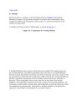
[ Team LiB ] 2.4 Instances A module provides a template from which you can create actual objects. When a module is invoked, Verilog creates a unique object from the template. Each object has its own name, variables, parameters, and I/O interface.
Chủ đề:
Bình luận(0) Đăng nhập để gửi bình luận!
Lưu
CÓ THỂ BẠN MUỐN DOWNLOAD


TRỢ GIÚP
HỖ TRỢ KHÁCH HÀNG
Theo dõi chúng tôi


Chịu trách nhiệm nội dung:
Nguyễn Công Hà - Giám đốc Công ty TNHH TÀI LIỆU TRỰC TUYẾN VI NA
LIÊN HỆ
Địa chỉ: P402, 54A Nơ Trang Long, Phường 14, Q.Bình Thạnh, TP.HCM
Hotline: 093 303 0098
Email: support@tailieu.vn
Giấy phép Mạng Xã Hội số: 670/GP-BTTTT cấp ngày 30/11/2015 Copyright © 2022-2032 TaiLieu.VN. All rights reserved.

