


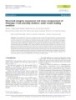
Structural integrity assessment and stress measurement of CHASNUPP-1 fuel assembly Part A: under tensile loading condition
14
lượt xem 1
download
lượt xem 1
download
 Download
Vui lòng tải xuống để xem tài liệu đầy đủ
Download
Vui lòng tải xuống để xem tài liệu đầy đủ
This study has been made in an attempt to find the structural integrity of the fuel assembly (FA) of Chashma Nuclear Power Plant-1 (CHASNUPP-1) at room temperature in air.
Chủ đề:
Bình luận(0) Đăng nhập để gửi bình luận!
Lưu
CÓ THỂ BẠN MUỐN DOWNLOAD


TRỢ GIÚP
HỖ TRỢ KHÁCH HÀNG
Theo dõi chúng tôi


Chịu trách nhiệm nội dung:
Nguyễn Công Hà - Giám đốc Công ty TNHH TÀI LIỆU TRỰC TUYẾN VI NA
LIÊN HỆ
Địa chỉ: P402, 54A Nơ Trang Long, Phường 14, Q.Bình Thạnh, TP.HCM
Hotline: 093 303 0098
Email: support@tailieu.vn
Giấy phép Mạng Xã Hội số: 670/GP-BTTTT cấp ngày 30/11/2015 Copyright © 2022-2032 TaiLieu.VN. All rights reserved.

