


Thiết kế và thực hiện hệ thống VLSI - 02
98
lượt xem 24
download
lượt xem 24
download
 Download
Vui lòng tải xuống để xem tài liệu đầy đủ
Download
Vui lòng tải xuống để xem tài liệu đầy đủ
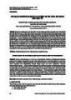
In equilibrium, the drift and diffusion components of current are balanced; therefore the net current flowing across the junction is zero.
Chủ đề:
Bình luận(0) Đăng nhập để gửi bình luận!
Lưu
CÓ THỂ BẠN MUỐN DOWNLOAD


TRỢ GIÚP
HỖ TRỢ KHÁCH HÀNG
Theo dõi chúng tôi


Chịu trách nhiệm nội dung:
Nguyễn Công Hà - Giám đốc Công ty TNHH TÀI LIỆU TRỰC TUYẾN VI NA
LIÊN HỆ
Địa chỉ: P402, 54A Nơ Trang Long, Phường 14, Q.Bình Thạnh, TP.HCM
Hotline: 093 303 0098
Email: support@tailieu.vn
Giấy phép Mạng Xã Hội số: 670/GP-BTTTT cấp ngày 30/11/2015 Copyright © 2022-2032 TaiLieu.VN. All rights reserved.

