


Gas Station Construction and Maintenance, Petroleum systems Contractor Nevada and Arizona_8
lượt xem 7
download
 Download
Vui lòng tải xuống để xem tài liệu đầy đủ
Download
Vui lòng tải xuống để xem tài liệu đầy đủ
Tham khảo tài liệu 'gas station construction and maintenance, petroleum systems contractor nevada and arizona_8', kỹ thuật - công nghệ, cơ khí - chế tạo máy phục vụ nhu cầu học tập, nghiên cứu và làm việc hiệu quả
Bình luận(0) Đăng nhập để gửi bình luận!
Nội dung Text: Gas Station Construction and Maintenance, Petroleum systems Contractor Nevada and Arizona_8
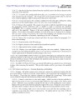
- UFC 3-460-03 Simpo PDF Merge and Split Unregistered Version - http://www.simpopdf.com 21 JANUARY 2003 Figure 9.2. Typical Method of Grounding Pier, Floating, and Barge Facilities. 95
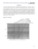
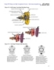
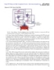
- UFC 3-460-03 Simpo PDF Merge and Split Unregistered Version - http://www.simpopdf.com 21 JANUARY 2003 Figure 9.3. Typical Method of Bonding Ladders on Floating Roof Tanks. 9.5.2. Pier Facilities. Before starting unloading operations from a barge or tanker, and before hose connections are made, securely bolt the ground wire on the dock to a clean, paint-free surface on the discharge line of the ship. 9.5.2.1. After this ground has been established, close the switch on the dock, completing the circuit. Maintain the circuit until offloading has been completed and hoses have been disconnected. See Figure 9.2. for typical grounding and bonding procedures. When the existing number 4 AWG copper (stranded cable) or copper alligator clamps need replacing, use 2.3-millimeter (0.09-inch) corrosion-resistant, plastic-covered steel cables (NSN 4010-00-286-2681 and MS 27610 Clip, Electrical Ground, NSN 5999-00-94-5844, respectively). 9.5.2.2. Periodically check all ground-connection cables, switches, and bonding jumpers for contact condition and tightness, as specified in paragraph 10.23. 9.5.3. Tank Car Loading and Unloading Facilities. When a tank car is being loaded, securely attach the grounding cable to a clean connection on the car before opening any valve or dome cover, or connecting the fuel hose. There is no requirement to connect a grounding cable between the tank car and stand or fuel line header during unloading operations because adequate grounding is provided to the rails without the use of the grounding cable. 9.5.4. Truck Fill Stand and Unloading Facilities. Under some atmospheric conditions, a truck in motion builds up a considerable charge of static electricity. Attach the grounding cable before opening the fill hatch or outlet valve or connecting the fuel hose. Figure 9.4 shows a typical bonding cable system and grounding details. Ground rod B is near the base of the fill stand. As soon as loading or unloading operations are completed and the fuel hose is detached from the vehicle, disconnect the ground conductor. Make periodic inspections to ensure tight bonding and good 96
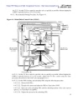
- UFC 3-460-03 Simpo PDF Merge and Split Unregistered Version - http://www.simpopdf.com 21 JANUARY 2003 ground conditions always exist. Maintain and test the grounding components as outlined in paragraph 10.23 and T.O. 00-25-172. When replacement of the existing number 4 AWG copper- stranded cable becomes necessary, use 2.3-millimeter (0.09-inch) stainless steel wire rope, nylon- covered (NSN 4010-00-286-2681). Figure 9.4. Truck Fill Stand and Unloading Area Grounding. 97
- UFC 3-460-03 Simpo PDF Merge and Split Unregistered Version - http://www.simpopdf.com 21 JANUARY 2003 9.5.5. Truck Fill Stand Grounding Assembly. 9.5.5.1. The assembly modification to the truck fill stand is done by the BCE from local resources, along with the FMF. Funding for materials is available from DESC. Visit the DESC home page at http://www.desc.dla.mil/default.asp. 9.5.5.2. The grounding assembly is installed and must be attached to a permanent structure of the fill stand, readily available for the refueler operator, and must be electrically interconnected to an existing approved static ground. The fixture uses the standard grounding hardware already installed on the refueler's reel cables. The design provides extra features that make the receptacles available from either direction of entry, and automatically disconnects if the vehicle is accidentally driven off; it also includes additional receptacles in case of a jack failure. 9.5.5.3. The aluminum T-bar may be attached to any type of surface (painted or bare metal) with standard cadmium-plated nuts and bolts. A number 10 or larger solid copper wire should interconnect with the assembly lug and approved static ground. Galvanic corrosion between two different types of metals will be minimal and have little effect on the assembly. 9.5.6. Hydrant Fueling Systems. 9.5.6.1. Where hydrant systems are grounded, it may be convenient to use a galvanized steel combination ground rod tie-down anchor (at least 16 millimeters [0.625 inch] in diameter by 2.4 meters [8 feet] in length) that is convenient to the aircraft. For Type II systems, it is centered between the hydrant outlet box and the electrical junction box paving. The surface of the paving should be cupped out to provide accessibility. 9.5.6.2. Provide a standard electrical ground clip on one end of the grounding cable. This connecting fitting should provide positive gripping by the clip’s teeth only, so that it must be opened to be removed. 9.5.6.3. Some Type II and III systems permanently bond the piping at the hydrant outlet to a driven ground rod (Type II systems also bond to the electric conduit at the electrical junction- receptacle box) with 1/0 copper bonding cable and approved grounding clamps. Usually, cathodic protection is applied to the hydrant system underground piping to retard corrosion. When the hydrant outlet is bonded to a ground rod, the outlet must be electrically isolated from the cathodically protected piping system at the first pair of flanges below the outlet. This is required to prevent shorting of the cathodic protection system, thereby making it ineffective. NOTE: Where cathodic protection is installed, and the hydrant outlet valve is grounded, it is extremely important to periodically verify the integrity of the isolation flange. 9.5.6.4. Use at least 15.8 millimeters [0.625 inch] in diameter by 2.4 meters [8 feet] in length galvanized steel rods with tie-down rings (or Shepherd’s hooks), for static grounds. For bare base and remote locations, use ground rod NSN 5975-00-240-3859. 9.5.6.5. Resistance of an approved static ground may be as high as 10,000 ohms, although a lower resistance is usually experienced. 9.6. Electrical Currents. Electrical currents originate in generators, transmission systems, wiring, and electrical devices. They are more dangerous than static charges because of the continuous electrical spark compared with the brief spark of a static charge. Observe the following precautions to eliminate the hazard of electrical currents. Verify that all electrical work on petroleum storage and dispensing systems complies with the NEC for Class I liquids. This is required by NFPA 407 2-4.9, Standard for 98
- UFC 3-460-03 Simpo PDF Merge and Split Unregistered Version - http://www.simpopdf.com 21 JANUARY 2003 Aircraft Fuel Servicing, which requires all electrical equipment and wiring to comply with NFPA 70, Article 515, Using Class 1 Liquids Requirements, for all applications. 9.7. Stray Currents. 9.7.1. General Information. Stray currents flow through different paths than the intended circuits, or are any extraneous current in the earth. Sources of stray currents include electric railways, electric power systems, electric welders, cathodic protection systems, and aircraft aeronautics electrical equipment malfunctions. Since Air Force fixed refueling systems are in intimate contact with the earth, stray currents sometimes take paths through the conducting parts of the system. 9.7.2. Hazards Due to Stray Currents. Stray currents cause arcs that will ignite combustible fuel-air mixtures. 9.7.3. Eliminating Hazards Due to Stray Currents. The grounding and bonding method used for reducing static hazards is important in eliminating stray current hazards. This does not eliminate stray currents, but does ensure a continuous path is provided to conduct them into the earth without arcing. 9.7.4. Tank Car Loading and Unloading Facilities. Railroad spurs, used for loading and unloading tank cars, should be insulated from the main line rails, so isolating them from stray currents that may flow in the main line rails. 9.7.5. Marine Terminals. Stray currents from cathodic protection systems at marine terminals require special attention. These systems, used for protecting piping and steel piers, cause currents to flow in the water. The steel hull of the vessel acts as a conductor of these currents. The ship-to-shore fuel-handling hose constitutes a conductor as it contains reinforcing wire, and will complete a low- resistance circuit from the vessel to the shore-side piping. Arcs may then occur between the vessel and the hose when the hose is connected, disconnected, or brought into contact with the vessel's deck. To prevent arcing, a grounding cable is connected between the shore-side piping and the vessel before operations begin. A switch wired in series with the cable is closed after the cable connection is made, and before the fuel handling hose is taken aboard the vessel. Any stray current flows from the vessel to shore by the cable, and arcing is avoided at the fuel handling hose and its connections (Figure 9.2). 9.7.6. Piping. Stray current may flow through piping systems because its electrical resistance is low compared to the surrounding earth. When removing any section of piping, valve, meter, or other component that will interrupt the continuity of the system, first install a bonding jumper wire. This jumper, installed around the component to be removed, will prevent an arc when the component is removed. 9.8. Electrical Inspection, Testing, and Identification Procedures. 9.8.1. Approved Static Grounds. Approved static grounds are provided for conducting electrostatic charges and stray electrical currents to earth or ground potential. These electrostatic voltages may be as high as 50,000 volts with low currents, and consequently the static ground resistance may be as high as 10,000 ohms. The purpose of an approved static ground interconnected with aircraft and support equipment is to place all components of the system to equal electrical potential to prevent arcing. 9.8.2. Identifying and Marking Static Grounds. All static grounds referenced in this manual will have a resistance of less than 10,000 ohms. All existing static grounds will have a one-time test with 99
- UFC 3-460-03 Simpo PDF Merge and Split Unregistered Version - http://www.simpopdf.com 21 JANUARY 2003 resistance values permanently recorded. Any static ground with a resistance greater than 10,000 ohms will be removed or replaced. Any static ground mechanically damaged will be repaired and retested. Static grounds do not need to be tested periodically after the initial test. 100
- UFC 3-460-03 Simpo PDF Merge and Split Unregistered Version - http://www.simpopdf.com 21 JANUARY 2003 Chapter 10 RECURRING WORK PROGRAM (RWP) 10.1. General Information. The safe, efficient, and economical operation of petroleum storage, dispensing systems, and associated infrastructure depends largely on an effective and proactive recurring maintenance program. An installation’s ability to accomplish its mission is increasingly dependent on a fully operational POL system. The recurring work program (RWP) is the most effective means of ensuring these critical systems are maintained at elevated in-service rates. The guidance in this chapter provides standardized procedures for servicing and inspecting POL systems and components. This chapter establishes the required frequency intervals for the recurring maintenance program. Deviations from the required frequencies listed in this chapter require prior approval by the applicable MAJCOM Petroleum Facility Engineer. Refer to Air Force Pamphlet (AFPAM) 32-1004, Volume 2, Working in the Operations Flight - Maintenance Engineering, Chapter 8, for an explanation of the preventive maintenance methodology used by the CE community. 10.2. Responsibilities. 10.2.1. The CE LFM shop, with assistance from the Maintenance Engineering shop, is responsible for developing an effective recurring maintenance program. The LFM shop foreman is responsible for accurately identifying and inventorying all fuel system components requiring recurring maintenance. The LFM shop foreman is responsible for the timely completion of all maintenance actions identified in the RWP program. 10.2.2. Many components throughout the POL system require some level of operator maintenance as identified in T.O. 37-1-1. The LFM shop foreman should be familiar with these operator maintenance requirements and verify the work is performed properly. Operator maintenance actions are not considered as preventative in nature and are not to be used to adjust the RWP program. 10.2.3. Representatives of the LFM shop and the FMF will inspect all petroleum systems weekly. At least one inspection each month will include the LFM shop foreman and the FMF commander (FMF/CC) or designated representative. During the inspection, a status review of all outstanding work will be conducted. The LFM shop foreman will verify that discrepancies are correctly annotated and have a work order number assigned. 10.2.4. The LFM shop foreman is responsible for coordinating with the FMF and other applicable agencies before performing recurring maintenance that may affect mission accomplishment. 10.3. Recurring Maintenance and Inspections. The following paragraphs describe recurring maintenance requirements performed by CE personnel. The required maintenance frequencies are shown in bold type at the end of the paragraph or subparagraph. Use Table 10.1 as a quick-reference chart to locate the paragraphs in this manual describing the preventive maintenance for each item. 101
- UFC 3-460-03 Simpo PDF Merge and Split Unregistered Version - http://www.simpopdf.com 21 JANUARY 2003 Table 10.1. Preventive Maintenance References. Item Paragraph Frequency Automatic Control Valves 10.3.24.1 Type I System HLSO 124AF 10.3.24.1.1 Semi-annually Non-surge/Check 81AF 10.3.24.1.2 Semi-annually FSCV 40AF-2A 10.3.24.1.3 Semi-annually Fuel/Defuel 302AF 10.3.24.1.4 Quarterly 10.3.24.2 Type II System Refuel Control 90AF-8 10.3.24.2.1 Quarterly Defuel Control 134AF 10.3.24.2.2 Quarterly Rate-of-Flow 41AF 10.3.24.2.3 Quarterly Pressure Relief 50AF-2 10.3.24.2.4 Semi-annually HLSO 129AF 10.3.24.2.5 Semi-annually Non-surge/Check 81AF-8 10.3.24.2.6 Semi-annually 10.3.24.3 Type II System (Modified) Rate-of-Flow 41AF-10 10.3.24.3.1 Quarterly Pressure Relief 51AF-4 10.3.24.3.2 Quarterly 10.3.24.4 Type III System HLSO 413AF-5A 10.3.24.4.1 Semi-annually Rate-of-Flow 41AF-1A 10.3.24.4.2 Semi-annually FSCV 41AF-2C 10.3.24.4.3 Semi-annually BPCV 58AF-9 10.3.24.4.4 Quarterly D/FV 58AF-9-1 10.3.24.4.5 Quarterly PCV 58AF-3 10.3.24.4.6 Quarterly HCV 362AF-8 10.3.24.4.7 Quarterly ESOV 136AF-9B 10.3.24.4.8 Quarterly 10.3.24.5 Type IV System (Hot Pit) HLSO 129AF-3A 10.3.24.5.1 Semi-annually D/FV 58AF-9-1 10.3.24.5.2 Quarterly Pantograph PCV 58E-47 10.3.24.5.3 Quarterly 102
- UFC 3-460-03 Simpo PDF Merge and Split Unregistered Version - http://www.simpopdf.com 21 JANUARY 2003 HCV 362AF-7 10.3.24.5.4 Quarterly ESO 136AF-9B 10.3.24.5.5 Quarterly Flush Valve 136AF-5A 10.27.5.6 Quarterly Hoses Prior to initial installation and as determined by the LFM Offloading 10.3.2.1 supervisor and local environmental requirements. Prior to initial installation and as determined by the LFM supervisor and local environmental requirements. Issue 10.3.2.2 When an API 1529 hose is delivered with a hydrostatic certification from the manufacturer, initial testing is not required. Manual Valves Lubricated plug 10.3.8.1 Quarterly Gate 10.3.8.2 Quarterly Non-lubricated plug 10.3.8.3 Quarterly Ball 10.3.8.4 Quarterly Meters Master meter 10.3.12.1 Annually Meter calibration 10.3.12.2 Annually Drain water 10.3.12.3 Weekly Miscellaneous System areas 10.3.1 As required Surge suppressors 10.3.11 Quarterly Signs and markings 10.3.13 Annually Pressure relief 10.3.14 Annually Service station dispensers 10.3.15 Quarterly Direct-reading gauge 10.3.16 Annually DP/PI transmitter 10.3.17 Semi-annually Cathodic protection 10.3.18 As required PPE 10.3.19 Annually or before use 103
- UFC 3-460-03 Simpo PDF Merge and Split Unregistered Version - http://www.simpopdf.com 21 JANUARY 2003 Electrical components 10.3.20 Quarterly Hydrant adapters 10.3.21 Semi-annually Auto tank gauge 10.3.22 Annually Strainer 10.3.23 As required Piping Pressure test 10.3.6.1 Annually Hydrostatic test 10.3.6.2 Every 5 years Exposed piping 10.3.6.3 Corrosion control 10.3.6.3.1 Semi-annually Identification 10.3.6.3.2 Quarterly Pumps General maintenance 10.3.7.1 Quarterly Lubrication 10.3.7.2 Quarterly or per manufacturer Product recovery 10.3.7.3 Quarterly Storage Tanks Vacuum/pressure vent 10.3.4 Semi-annually Dikes 10.3.5 Annually Aboveground 10.3.3.1 Visual inspection 10.3.3.1.1 Monthly API 653 10.3.3.1.2 Every 10 years Floating roof/pan 10.3.3.2 Seals and pan 10.3.3.2.1 Monthly Roof drain 10.3.3.2.2 Monthly Roof drain (antifreeze) 10.3.3.2.4 As required Cleaning/inspection 10.3.3.3 Without F/S and coating 10.3.3.3.1 Every 4 years With F/S or coating 10.3.3.3.2 Every 6 years With F/S and coating 10.3.3.3.3 Every 8 years 10.3.1. System Areas. Large grass-covered areas around fuel systems will be mowed by BCE personnel or by service contract. Consult the Maintenance Engineering shop for questions concerning performance of this task by contract. FREQUENCY: As required. 10.3.2. Hoses. 104
- UFC 3-460-03 Simpo PDF Merge and Split Unregistered Version - http://www.simpopdf.com 21 JANUARY 2003 10.3.2.1. Offloading Hoses. For truck or tank car offloading areas, use 101-millimeter (4-inch) lightweight, reinforced, vacuum-rated offloading hoses (see MIL-HDBK-1022A). Test per the manufacturer’s instructions. FREQUENCY: Prior to initial installation and as determined by the LFM supervisor and local environmental requirements. 10.3.2.2. Issue Hoses. Truck fill stand, marine off-loading, and aircraft refueling hoses must meet the standards of API 1529. Hydrostatically test to one and one-half times the dead head (shutoff head) pressure of the system, not to exceed the maximum working pressure of the hose. NOTE: Hydrostatic hose testing for real property installed equipment (RPIE) is a joint operator/LFM responsibility, yet primary responsibility lies with the LFM shop foremen. The LFM shop maintains hydrostatic test records and performs the test. Mutual arrangements for hose testing by the refueling maintenance (RFM) shop is authorized and encouraged where possible. Ground product hoses with working pressures less than 20 psi do not require pressure testing. FREQUENCY: Prior to initial installation and as determined by the LFM shop foreman, local environmental requirements, and manufacturer’s recommendation. When an API 1529 hose is delivered with a hydrostatic certification from the manufacturer, initial testing is not required. 10.3.3. Storage Tanks. 10.3.3.1. Aboveground Field-Constructed Tanks. 10.3.3.1.1 Visual Inspection. Visually check the exterior of each tank for leaks, corrosion, or irregularities such as tilting, settling, or out-of-roundness. Give special attention to seams and anchor bolts. Maintain a waterproof seal at the tank chime-ring wall foundation interface. Retain records in the LFM shop for five years. Scrape, clean, and repaint rusted or corroded areas. FREQUENCY: Monthly. 10.3.3.1.2. Out-of-Service API 653 Inspection. Use nondestructive techniques to inspect all metallic surfaces, including the floor. FREQUENCY: Every 10 years. 10.3.3.2. Floating Roof or Pan. 10.3.3.2.1. Clean and check perimeter tank seals; check centering of roof or pan. The performance of this task may require a confined space entry. FREQUENCY: Monthly. 10.3.3.2.2. For open-top floating-roof tanks, ensure the center primary roof drain system is water-free, the drip-tight plug is placed in the roof drain opening, and the roof drain valve is closed. The drain valve is kept in the closed position except after each rain or snowfall when it will be opened just long enough to drain the roofline. FREQUENCY: Monthly. 10.3.3.2.3. The LFM shop foreman is responsible for training FMF personnel on procedures for draining floating-roofs and interior dike basins. Once trained, FMF retains responsibility for draining roof drains and interior dike basins. 10.3.3.2.4. At locations where freezing conditions are encountered, the LFM shop will fill the floating-roof tank drain line with antifreeze or deicing fluid. Periodically test the 105
- UFC 3-460-03 Simpo PDF Merge and Split Unregistered Version - http://www.simpopdf.com 21 JANUARY 2003 antifreeze or deicing fluid for proper protection and record results. The roof drain valve must be secured and will have a sign attached to it stating: CAUTION - WINTERIZED - DO NOT DRAIN FREQUENCY: As Required. 10.3.3.3. Tank Inspection/Cleaning Requirements (Aviation Products). Operating and bulk storage tanks have identical inspection/cleaning frequencies. Follow governing environmental regulations if more stringent. Complete AF Form 172 and submit it to the MAJCOM fuels facility engineer. 10.3.3.3.1. Tanks without an inlet F/S, micronic filter on the inlet, or internal coating. FREQUENCY: Every 4 years. 10.3.3.3.2. Tanks with F/S or micronic filter on the inlet or internal coating. FREQUENCY: Every 6 years. 10.3.3.3.3. Tanks with F/S or micronic filter on the inlet and internal coating, or built to the standard design. FREQUENCY: Every 8 years. This may be extended to coincide with the API 653 out- of-service inspection every 10 years after the first inspection is completed. 10.3.4. Tank Vacuum and Pressure Vents. Inspect, clean, and repair. Where applicable, inspect antifreeze levels in the spring and fall. A mixture of equal parts of water and antifreeze will be used. FREQUENCY: Semi-Annually. 10.3.5. Dikes. 10.3.5.1. Earthen. 10.3.5.1.1. Inspect for signs of erosion and vegetation. FREQUENCY: Annually. 10.3.5.1.2. Use fireproof chemicals for sterilization of dikes and basins to prevent growth of vegetation. Work should be done by BCE entomology personnel or by contract. FREQUENCY: As required. 10.3.5.2. Concrete, Asphalt, or Cement Brick. Inspect condition and repair as required. FREQUENCY: Annually. 10.3.6. Piping. 10.3.6.1. Pressure Test. Pressurize all on-base fuel piping systems using existing system pumps. When conducting the test, follow the guidance outlined in paragraph 2.3.3.1. FREQUENCY: Annually. 10.3.6.2. Hydrostatic Test. Perform a hydrostatic pressure test on all underground fuel transfer lines. Product is normally the test media. Details for conducting the test are provided in paragraph 2.3.3.2. Consult your fuels facility engineer for guidance on completing this requirement. The fuels facility engineer is the approving authority for all waivers of this requirement. Dual pressure temperature compensating pressure test methods may be considered with approval from the MAJCOM fuels engineer. This method may allow the test to be conducted faster with fewer blind flanges than the traditional hydrostatic pressure test described in paragraph 2.3.3.2. FREQUENCY: Every 5 years. 10.3.6.3. Exposed Piping. 106
CÓ THỂ BẠN MUỐN DOWNLOAD

-
Gas Station Construction and Maintenance, Petroleum systems Contractor Nevada and Arizona_2
 12 p |
  63
|
63
|  7
7
-
Gas Station Construction and Maintenance, Petroleum systems Contractor Nevada and Arizona_12
12 p | 61
| 5
-
Gas Station Construction and Maintenance, Petroleum systems Contractor Nevada and Arizona_11
12 p | 60
| 5
-
Gas Station Construction and Maintenance, Petroleum systems Contractor Nevada and Arizona_9
12 p | 49
| 4
-

Gas Station Construction and Maintenance, Petroleum systems Contractor Nevada and Arizona_1
12 p | 57
| 4
-
Gas Station Construction and Maintenance, Petroleum systems Contractor Nevada and Arizona_4
12 p | 63
| 4
-
Gas Station Construction and Maintenance, Petroleum systems Contractor Nevada and Arizona_5
12 p | 52
| 3
-
Gas Station Construction and Maintenance, Petroleum systems Contractor Nevada and Arizona_7
12 p | 41
| 3
-
Gas Station Construction and Maintenance, Petroleum systems Contractor Nevada and Arizona_10
12 p | 67
| 3
-
Gas Station Construction and Maintenance, Petroleum systems Contractor Nevada and Arizona_3
12 p | 55
| 3
-
Gas Station Construction and Maintenance, Petroleum systems Contractor Nevada and Arizona_6
12 p | 72
| 3


Chịu trách nhiệm nội dung:
Nguyễn Công Hà - Giám đốc Công ty TNHH TÀI LIỆU TRỰC TUYẾN VI NA
LIÊN HỆ
Địa chỉ: P402, 54A Nơ Trang Long, Phường 14, Q.Bình Thạnh, TP.HCM
Hotline: 093 303 0098
Email: support@tailieu.vn
Giấy phép Mạng Xã Hội số: 670/GP-BTTTT cấp ngày 30/11/2015 Copyright © 2022-2032 TaiLieu.VN. All rights reserved.

