


Gas Station Construction and Maintenance, Petroleum systems Contractor Nevada and Arizona_9
lượt xem 4
download
 Download
Vui lòng tải xuống để xem tài liệu đầy đủ
Download
Vui lòng tải xuống để xem tài liệu đầy đủ
Tham khảo tài liệu 'gas station construction and maintenance, petroleum systems contractor nevada and arizona_9', kỹ thuật - công nghệ, cơ khí - chế tạo máy phục vụ nhu cầu học tập, nghiên cứu và làm việc hiệu quả
Bình luận(0) Đăng nhập để gửi bình luận!
Nội dung Text: Gas Station Construction and Maintenance, Petroleum systems Contractor Nevada and Arizona_9
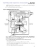
- UFC 3-460-03 Simpo PDF Merge and Split Unregistered Version - http://www.simpopdf.com 21 JANUARY 2003 10.3.6.3.1. Check all exposed piping, valves, and associated equipment for corrosion. Prepare the surface and repaint as necessary. FREQUENCY: Semi-Annually. 10.3.6.3.2. Piping identification must conform to MIL-STD-161. Repaint as necessary. FREQUENCY: Quarterly. 10.3.7. Pumps. 10.3.7.1. Check for unusual noise, vibration, over-heating, leaks, and oil level. FREQUENCY: Quarterly. 10.3.7.2. Lubricate pumps and motors as recommended by the manufacturer. NOTE: Excessively greased bearings can cause over-heating. FREQUENCY: Quarterly, or as recommended by the manufacturer. 10.3.7.3. Product Recovery Tank Pump. The pump should start when the liquid level reaches 70% of the tank’s total capacity, and shut off when the level is pumped down to 20%. FREQUENCY: Quarterly. 10.3.8. Manual Valves. 10.3.8.1. Lubricated Plug. Inspect all lubricated plug valves for ease of operation. If lubrication is needed due to difficult operation, replace the valves immediately with non-lubricated valves. All lubricated plug valves must be scheduled for replacement. FREQUENCY: Quarterly. 10.3.8.2. Gate. Lubricate and operate to prevent seizing. Adjust/replace packing as needed. FREQUENCY: Quarterly. 10.3.8.3. Non-Lubricated Plug Valves. Inspect for ease of operation. Adjust packing and maintain operators per manufacturer’s specifications. FREQUENCY: Quarterly. 10.3.8.4. Ball. Inspect for ease of operation and lubricate operators. FREQUENCY: Quarterly. 10.3.9. Filter Separator (F/S). 10.3.9.1. F/S Element. At the last point of filtration in the fixed system, replace elements at 15 psi DP, or every three years, whichever comes first. Replace elements at all other locations at 20 psi DP, or every three years, whichever comes first. During element replacement, clean the interior surfaces of the F/S vessel and second-stage element(s) (see paragraph 3.3 for detailed instructions). Use API edition 4 or 5 elements. Funding will be provided by DESC. 10.3.9.2. Determining DP. DP is measured at the rated flow of the vessel (e.g., 20 psi at 2271 liters per minute [600 gallons per minute]). If two 2271-liter-per-minute pumps discharge through four F/Ss, then a DP of 10 psi at 1135 liters per minute (300 gallons per minute) would be equal to 20 psi at 2271 liters per minute. Before changing out elements, verify the pressure drop at 2271 liters per minute by isolating the F/S so it receives a flow of 2271 liters per minute and measure the DP. This is particularly critical with Type III systems where fuel from a varying number of pumps flows through multiple F/Ss. In older systems where a 4542-liter-per- minute (1200-gallon-per-minute) filter vessel is dedicated to a 2271-liter-per-minute pump, change out the elements as if it were a 2271-liter-per-minute vessel. If the DP across a vessel suddenly drops 3 psi or more at the same flow rate, check the vessel for a damaged element. 107
- UFC 3-460-03 Simpo PDF Merge and Split Unregistered Version - http://www.simpopdf.com 21 JANUARY 2003 NOTE: Before placing the F/S back in service, contact the FMF to ensure flushing and sampling is accomplished (see T.O. 42B-1-1, Quality Control of Fuels and Lubricants). 10.3.10. Micronic Filter. Determine filter element replacement by manufacturer data, or after 757,082 liters (200,000 gallons) of fuel have passed through the elements, whichever occurs first. The MAJCOM fuels engineer may extend the filter replacement based on DP for high through-put installations. 10.3.11. Surge Suppressors. Check pressure settings and adjust in accordance with the manufacturer’s specifications. FREQUENCY: Quarterly. 10.3.12. Testing and Calibrating Meters. Component wear and accumulation of solids make periodic calibration necessary. 10.3.12.1. Certified master meters are used for meter calibration by connecting hoses from the hydrant outlet or fill stand to the master meter, and from the master meter to a tank truck or servicing vehicle. Calibrate master meters annually. 10.3.12.2. Test meters at a predetermined flow rate and at calibration settings between 20% and 100% capacity. Meters are satisfactory when the meter error in the normal flow direction is within ±0.2% of actual quantity delivered (e.g., ±1.2 gallons for a 600-gallon test ). Calibrate service station meters to within ±0.2%. Adjust meters according to manufacturer’s recommendations. Use stencils or embossing tape to permanently mark the installed meters. FREQUENCY: Annually. 10.3.12.3. Meters with installed drain plugs will be drained of water and sediment by FMF personnel. The LFM shop foreman will ensure drainable meters have the proper connections installed. FREQUENCY: Weekly. 10.3.13. Signs and Markings. Check signs and markings for adequacy and readability. See AFOSH Std 91-38, Section 3.2, for descriptions of sign locations, and MIL-STD-161F2, Identification Methods for Bulk Petroleum Products Systems Including Hydrocarbon Missile Fuels, for marking requirements. FREQUENCY: Annually. 10.3.14. Pressure Relief. Check system pressure relief to ensure proper operation. Test and/or adjust the pressure relief valve 10% above system deadhead pressure, not to exceed 275 psi. Repeat the test, if applicable, a minimum of three times to ensure proper operation. Not all pressure relief valves are set at 10% above the maximum operating pressure. Thermal relief valves must be set to allow cascading of pressure back to the storage tank. In this case use set points specified in construction documentation. FREQUENCY: Annually. 10.3.15. Service Station Dispensers. Check operation, belt alignment, strainer, linkage operations, hoses, meter calibration, relief assembly, and automatic nozzle shutoff functions. FREQUENCY: Quarterly. 10.3.16. Direct-Reading/DP Gauges. Calibrate according to the manufacturer’s specifications. NOTE: Piston-type DP gauges require calibration only at USAFE bases. Calibration procedures are in NATO STANAG 3583, Standards of Accuracy for Different Press Gauges for Aviation Fuel Filters and Filter/Separators. 108
- UFC 3-460-03 Simpo PDF Merge and Split Unregistered Version - http://www.simpopdf.com 21 JANUARY 2003 FREQUENCY: Annually. 10.3.17. Differential Pressure Transmitter (DPT) and Pressure Indicating Transmitter (PIT). Calibrate mechanically and electrically with test equipment and adjust if applicable. Calibrate in accordance with manufacturer’s specifications. FREQUENCY: Semi-annually. 10.3.18. Cathodic Protection Systems. Cathodic protection is maintained by the base cathodic protection technician or by service contract. The LFM shop foreman will ensure the cathodic protection systems on the POL system are maintained by the base cathodic protection technician in accordance with UFC 3-570-06, Operation and Maintenance: Cathodic Protection Systems, and AFI 32-1054. Close interval (soil-to-structure potential) piping surveys should be conducted initially within 30 days of installation and every five years thereafter. FREQUENCY: As required. 10.3.19. Tank Entry, Confined Space Entry, and other Personal Protective Equipment (PPE). Inspect for serviceability, cleanliness, and deterioration. See Chapter 11 for detailed instructions. Service equipment in accordance with manufacturer’s specifications. FREQUENCY: Annually, or before use. 10.3.20. Electrical Equipment. Verify proper operation of all electrical equipment associated with the operation of the installation’s POL infrastructure. Identify necessary repairs to the zone or electrical section with responsibility for the area. Typical inspection items include, but are not limited to: Ground conductors Ground connections Starters and Contactors Circuit breakers Area lighting Grounding cables Disconnect switches Exposed wiring Emergency switches Flow switches FREQUENCY: Quarterly. 10.3.21. Hydrant Adapters. Check for leaks and damage. FREQUENCY: Semi-Annually. 10.3.22. Automatic Tank Gauges (ATG). Calibrate with test equipment and adjust as required. Ensure the gauge is free of moisture and debris. Many ATGs are maintained by contract under the Petrol Ram Contract. Contact the AFPET office for more information (see paragraph 6.3.2.7). FREQUENCY: Annually. 10.3.23. Strainer. Inspecting and cleaning system strainers is the responsibility of FMF personnel. The LFM shop will supply guidance and/or replacement parts as required. FREQUENCY: As required. 109
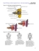
- UFC 3-460-03 Simpo PDF Merge and Split Unregistered Version - http://www.simpopdf.com 21 JANUARY 2003 10.3.24. Automatic Control Valves. Following is a list of valves by type of system and valve function. The numbers shown after each valve are Cla-Val designations. Actions and frequencies required below are not limited to Cla-Val, but apply to all manufacturers’ valves having the same function. Any automatic valves not listed will have a Quarterly RWP frequency. NOTE: The amount of maintenance required on the listed automatic valves will vary with each inspection. The intent of the inspection is to determine the valves proper operation and performance. If it is determined that the valve is operating correctly, pilot control adjustment and/or main valve calibration is not required. 10.3.24.1. Type I Panero System. 10.3.24.1.1. High Level Shut-Off Valve (HLSO) (124AF). When the tank is being filled, check for proper operation of the HLSO valve. Check high-level alarms with high-level control valves. Set valve to activate when the fuel level is approximately 11 inches from the top of the tank. this should be no more than 95% full. FREQUENCY: Semi-annually. 10.3.24.1.2. Non-Surge/Check Valve (81AF). Check opening speed (approximately 20 seconds) and check valve function. FREQUENCY: Semi-annually. 10.3.24.1.3. Fuel Shut-Off Control Valve (FSCV) (40AF-2A). 10.3.24.1.3.1. Flow Rate. Check flow rate. Flow rate is determined by F/S vessel gallon- per-minute rating, or element flow rate, whichever is less. FREQUENCY: Semi-annually. 10.3.24.1.3.2. Water Shut-off. Test FSCV, either by engaging the flanged float test button or lever while flowing fuel through the F/S, or by injecting water until the ball float is in the “up” position. Ensure the FSCV shuts off when the ball float is in the “up” position. When the mission mandates the use of water drain valves, check the drain valve operation also. Drain water immediately upon completing the test. CAUTION: When performing this test, only flow the minimum amount of fuel through the F/S to prevent system pressure spikes. Check FSCV on 50-gallon-per-minute product recovery tank pumps. Newer Type III systems have FSCVs with emergency shutdown capability. FREQUENCY: When elements are changed. 10.3.24.1.4. Fueling/Defueling Control Valve (302AF). Check both refueling and defueling control valve features. Check pressure-reducing control, pressure-relief control, opening rate, excess flow shutoff, defuel pressure-relief control, and solenoid operation. See Chapter 3 for pressure setting procedures. FREQUENCY: Quarterly. 10.3.24.2. Type II Pritchard System. 10.3.24.2.1. Refueling Control Valve (90AF-8). Check pressure-reducing control, pressure- relief control, opening rate, excess flow shutoff, and solenoid operation. See Chapter 4 for pressure setting procedures. For excess flow control, see Attachment 3. FREQUENCY: Quarterly. 10.3.24.2.2. Defuel Control Valve (134AF). Check solenoid operation. FREQUENCY: Quarterly. 110
- UFC 3-460-03 Simpo PDF Merge and Split Unregistered Version - http://www.simpopdf.com 21 JANUARY 2003 10.3.24.2.3. Rate-of-Flow Defuel Valve (41AF). Check rate of flow control and check valve function. Set flow rate at 200 gallons per minute. FREQUENCY: Quarterly. 10.3.24.2.4. Pressure Relief Valve (50AF-2). Check pressure-relief function. The typical pressure setting is 10 psi above normal inlet pressure for the 90AF-8. FREQUENCY: Semi-annually. 10.3.24.2.5. High-Level Shut-Off Valve (129AF). When the tank is being filled, check for proper operation of the high-level control valve. Check high-level alarms with high-level control valves. Set shut-off level at 11 inches from the top of the tank or 95% full, whichever is less. FREQUENCY: Semi-annually. 10.3.24.2.6. Non-Surge Check Valve (81AF-8). Check opening speed (about 20 seconds) and check valve function. FREQUENCY: Semi-annually. 10.3.24.3. Type II Modified Pritchard System. 10.3.24.3.1. Combination Rate-of-Flow, Solenoid Shutoff, and Check Valve (41AF-10). Check rate-of-flow control, check-valve function, and solenoid functions. Set at 200 gallons per minute. FREQUENCY: Quarterly. 10.3.24.3.2. Combination Dual Pressure Relief, Solenoid Shutoff, and Check Valve (51AF- 4). Check low- and high-pressure relief functions, check-valve function, solenoid functions, and closing speed control. See Chapter 5 for pressure setting procedures. FREQUENCY: Quarterly. 10.3.24.4. Type III Constant-Pressure Hydrant Fueling System (Phillips System). 10.3.24.4.1. High-Level Shut-Off Valve (413AF-5A). When the tank is being filled, check for proper operation of the high-level control valve. CAUTION: When testing, use the minimum flow rate necessary. FREQUENCY: Semi-annually. 10.3.24.4.2. Rate of Flow, Non-Surge Check Valve (41AF-1A). Check opening speed, flow rate, and check-valve function. The typical opening speed is approximately 20 seconds. The typical flow rate is 650 gallons per minute. FREQUENCY: Semi-annually. 10.3.24.4.3. Fuel Shut-off Control Valve (41AF-2C). Check rate of flow, check-valve function, and water shutoff features. The typical setting is 600 gallons per minute. FREQUENCY: Semi-annually. 10.3.24.4.4. Back Pressure Control Valve (58AF-9). Check pressure control, closing rate speed, solenoid operation, and check-valve function. The typical setting is 100 psi at the inlet of the furthest hydrant outlet, and set closing speed control as fast as possible while still maintaining smooth operation. NOTE: This valve typically uses a restrictor to aid in opening. FREQUENCY: Quarterly. 10.3.24.4.5. Defuel/Flush Valve (58AF-9-1). Check pressure relief, check-valve function, solenoid operation, and opening and closing speed controls. The typical pressure relief 111
- UFC 3-460-03 Simpo PDF Merge and Split Unregistered Version - http://www.simpopdf.com 21 JANUARY 2003 setpoint is 80 psi. Set the opening and closing speed control as fast as possible while still maintaining smooth operation. FREQUENCY: Quarterly. 10.3.24.4.6. Pressure Control Valve (58AF-3). Check pressure control, opening and closing rates, and solenoid operation. The typical setpoint is 75 psi. The typical opening and closing speed is 3 seconds. FREQUENCY: Quarterly. 10.3.24.4.7. Hydrant Control Valve (362AF-8). Check pressure-reducing control, pressure- relief control, opening speed, and deadman operation. NOTE: HCV is also located at the HSV check-out stand. FREQUENCY: Quarterly. 10.3.24.4.8. Emergency Shut-Off Valve (136AF-9B). Check solenoid operation, DP control, and quick-closing feature. Verify valve closes within 10 seconds. Solenoids are energized, except during power failures or when the ESO switch is activated. The typical setting for differential control is 7 psi. FREQUENCY: Quarterly. 10.3.24.4.9. Product Recovery Tank Overfill Valve (2129AF). Check the thermal-relief feature, overfill-protection operation, and ensure the pressure reservoir tank holds pressure. The typical setting for thermal relief is 200 psi. The OV must be set to close and sound an alarm in the control room when the tank is 80% full. Ensure the pressure reservoir tank holds the pump deadhead pressure when the pump is deactivated. NOTE: When the float in the tank rises and the OV changes position, the pressure in the pressure reservoir tank will decrease. FREQUENCY: Semi-annually. 10.3.24.5. Type IV Hot Pit Refueling System. 10.3.24.5.1. High-Level Shut-Off Valve (129AF-3A). When the tank is being filled, check for proper operation of the high-level control valve. This valve uses a fail-safe closed pilot system. This means that if the control line ruptures, the main valve will close. CAUTION: When testing, use the minimum flow rate necessary. FREQUENCY: Semi-annually. 10.3.24.5.2. Defuel/Flush Valve (58AF-9-1). Check pressure relief, check-valve function, solenoid operation, and opening and closing speed controls. The typical pressure relief setpoint is 100 psi. Set the opening and closing speed control as fast as possible while still maintaining smooth operation. FREQUENCY: Quarterly. 10.3.24.5.3. Pantograph Pressure Control Valve (PPCV) (58E-47). Check pressure control, opening and closing rates, and solenoid operation. The typical setpoint is 75 psi. The typical opening and closing speed is 3 seconds. FREQUENCY: Quarterly. 10.3.24.5.4. Hydrant Control Valve (362AF-7). Check pressure-reducing control, pressure- relief control, opening speed, and deadman operation. The typical setting for pressure- reducing control is 45 psi. The pressure-relief control must close within 5 seconds when system pressure reaches 50 psi. The typical opening speed is 20 seconds; however, to dampen the nozzle pressure wave, opening speed may be retarded. When the deadman is 112
- UFC 3-460-03 Simpo PDF Merge and Split Unregistered Version - http://www.simpopdf.com 21 JANUARY 2003 released, the deadman must close the valve within 5 seconds. NOTE: This valve is connected to the pantograph system and is hydraulically operated. FREQUENCY: Quarterly. 10.3.24.5.5. Emergency Shut-Off Valve (136AF-9B). Check solenoid operation, DP control, and quick-closing feature. Verify valve closes within 10 seconds. Solenoids are energized except during power failures or when the ESO switch is activated. The typical setting for the differential control is approximately 7 psi. FREQUENCY: Quarterly. 10.3.24.5.6. Flush Valve (136AF-5A). Check solenoid operation and quick-closing feature. Solenoid is de-energized when the system is placed in pantograph flush. FREQUENCY: Quarterly. 113
- UFC 3-460-03 Simpo PDF Merge and Split Unregistered Version - http://www.simpopdf.com 21 JANUARY 2003 Chapter 11 ENTRY FOR INSPECTING, CLEANING, REPAIRING, AND COATING LIQUID PETROLEUM TANKS 11.1. Introduction. This chapter provides minimum standards for safe entry, inspection, cleaning, repairing, and coating of liquid petroleum tanks. The names formally used to describe LFM tank- cleaning positions (tank cleaning supervisor, worker, manhole observer, fresh air blower monitor, safety [emergency] person) have been changed to align the LFM career field with the Air Force Confined Space Entry Program (CSEP). The new names: tank entry supervisor (TES); entrant; attendant; regulator monitor; and organizational rescue team (standby rescue personnel), respectively. 11.2. Standards. 11.2.1. For all tank cleaning and related functions, follow the guidance in API Std 2015, Safe Entry and Cleaning of Petroleum Storage Tanks, Planning and Managing Tank Entry from Decommissioning through Recommissioning. API Std 2015 contains a comprehensive planning checklist in Appendix E. The rest of the paragraphs in this chapter tailor guidance in the API publication to the LFM requirement. 11.2.2. The following AFOSH standards are to be used in lieu of the OSHA standards covered in the API publication: 11.2.2.1. AFOSH Std 91-25, Confined Spaces (49 CFR 1910.146, Permit-Required Confined Spaces). 11.2.2.2. AFOSH Std 91-31, Personal Protective Equipment (PPE). 11.2.2.3. AFOSH Std 91-38, Hydrocarbon Fuels, General. 11.2.2.4. AFOSH Std 48-137, Respiratory Protection Program. 11.2.2.5. AFOSH Std 48-8, Controlling Exposure to Hazardous Materials. 11.2.2.6. AFOSH Std 91-5, Cutting and Brazing. 11.3. TES Certification Requirements. The TES is responsible for all aspects of tank entry and must have an AF Form 483, Tank Cleaning Certificate of Competency card issued by the MAJCOM fuels engineer. Certification will not exceed five years from the completion date of the Air Education and Training Command (AETC) TES course. The MAJCOM fuels engineer may approve a one-year waiver. Certificates are not transferable between MAJCOMs. Submit the following to the MAJCOM fuels engineer for certification: 11.3.1. Certification of Training. Forward a copy of the AETC TES course completion certificate (AF Form 1256, Certificate of Training). This course is mandatory for certification and must be redone every five years. A one-year waiver may be approved by the MAJCOM fuels engineer to allow for scheduling difficulties. 11.3.2. Tank Cleaning Experience. List at least two tanks cleaned, showing dates, size, location, and tank-cleaning supervisor. 114
- UFC 3-460-03 Simpo PDF Merge and Split Unregistered Version - http://www.simpopdf.com 21 JANUARY 2003 11.3.3. Medical Evidence. Applicant is physically qualified to perform tank cleaning. 11.4. Tank Entry Personnel Requirements. 11.4.1. Medical Requirements. Prior to entry and or cleaning operations, each tank entrant (military or civilian) must have proof of a current physical (AF Form 600, Treatment Record, or equivalent), or an appropriate medical statement from the local medical facility stating the applicant is physically qualified to perform tank cleaning. Medical statements are valid for one year. Provide an AF Form 2772, Certificate of Respirator Fit Test, or equivalent showing the individual has been fit-tested to wear a respirator. 11.4.2. Health Effects. Colds, fatigue, overheating, or lowered physical resistance from any source increases a person's susceptibility to hazards encountered in tank entry. 11.4.3. Psychological Effects. Anyone with a medically documented history of claustrophobia will be disqualified from entering any tanks. 11.5. Confined Space Entry Requirements. AFOSH Std 91-25 contains requirements for practices and procedures that provide protection for Air Force employees (military and civilian) who enter and work within confined spaces. Information in AFOSH Std 91-25 is considered the Air Force’s minimum safety, fire prevention, and occupational health requirements. 11.6. Tank Cleaning Crew. 11.6.1. Crew Members. The typical crew size for tank entry is five: TES; entrant; attendant; regulator monitor (duties may be performed by the attendant if conditions allow); and organizational rescue team (standby rescue personnel). Additionally, a pump or compressor operator may be required. Individuals assigned these duties will not leave their positions until relieved by the TES. Any deviation from the above must be coordinated with the MAJCOM fuels engineer. 11.6.2. TES. The TES, also referred to as the entry (on-site) supervisor, is responsible for all aspects of tank entry and stays at the job site until all individuals have exited the tank. The TES only transfers supervisory responsibility when he or she enters the tank. Before entry, the TES appoints an equally qualified individual to run operations while he or she is in the tank. 11.6.2.1. The TES ensures all workers are properly trained on safe tank entry procedures, use of protective equipment, and ways to egress the confined space. 11.6.2.2. The TES must review as-built drawings to become familiarized with tank components and appurtenances. 11.6.2.3. Before starting any tank entry project, the TES briefs all members of the tank entry crew. The briefing includes: duties of each member; hazards affecting the entry; component inspection requirements; worker actions if there is an emergency; length of time each person will be in the tank; effects of inhalation; other health and safety aspects inherent to the entry. 11.6.2.4. The TES must follow the confined space entry procedures outlined in AFOSH Std 91-25, Paragraph 2.13. For additional information, use the planning checklist in AFOSH Std 91-25, Appendix E, as a guide to develop a site-specific work plan. 115
- UFC 3-460-03 Simpo PDF Merge and Split Unregistered Version - http://www.simpopdf.com 21 JANUARY 2003 11.6.3. Entrant. The entrant is the individual trained, qualified, and authorized to enter the confined space. Entrants must: 11.6.3.1. Fully understand all cleaning procedures, inspection requirements, safeguards, and emergency egress and or rescue procedures associated with the entry. 11.6.3.2. Follow all safe work procedures required by the TES. 11.6.3.3. Notify the TES when hazards exist that have not been corrected. 11.6.3.4. Notify the TES if he or she is ill or on medication. 11.6.3.5. Immediately exit the tank when directed by any member of the tank cleaning crew or when they recognize the warning signs of exposure to hazardous substances. 11.6.4. Attendant. The attendant stays outside the tank and monitors the entrants inside. The attendant should maintain continuous communication with all authorized entrants, by voice, visual observation, communications gear, or other equally effective means. 11.6.4.1. The attendant has the authority to order entrants out of the tank at the first sign of an unexpected hazard. 11.6.4.2. The attendant must know the procedure and have the means to summon emergency assistance if needed. They must stay at their post and not leave for any reason (except self- preservation) unless replaced by an equally qualified individual. 11.6.4.3. The attendant continuously monitors the atmospheric levels while the entrants are inside the tank. 11.6.5. Regulator Monitor. The regulator monitor is the individual that is responsible for ensuring an uninterrupted supply of breathing air is provided to all workers in the tank. Self-contained breathing apparatus (SCBA) systems must always be monitored while workers are inside the tank. If only minimum manning is available, the attendant can double as the regulator monitor. This individual must be able to see the gauges, hear the warning devices, and summon workers out of the tank if an unacceptable condition arises. Also, the regulator monitor must: 11.6.5.1. Be fully trained on the operation of the air regulator, alarms, warning devices, and proper setup of the air bottle or cascade system. 11.6.5.2. Ensure all equipment is in proper working order and has been thoroughly operationally checked prior to workers entering the tank. 11.6.5.3. Notify the attendant or TES of any condition that could hinder the supply of air to workers inside the tank. 11.6.5.4. Monitor air equipment and low-air warning devices until all workers exit the tank and remove their masks. 11.6.6. Organizational Rescue Team. This team includes the TES, attendant, and at least one stand- by rescue person for each individual inside the tank. . For aboveground storage tanks that are less than 12 meters (40 feet) in diameter with two open manways, only one stand-by rescue person is required for every two men in the tank. If two workers are inside the tank, then two rescue people will be standing by equipped with the appropriate PPE. All rescue personnel must meet the training requirements outlined in AFOSH Std 91-25, Paragraph 5.5, and the training requirements of the entrant. Members of the organizational rescue team can be trained locally or in technical school in the correct performance of their assigned duties. Also, members must be trained annually in CPR. 116
- UFC 3-460-03 Simpo PDF Merge and Split Unregistered Version - http://www.simpopdf.com 21 JANUARY 2003 CPR training will be documented on the individual’s AF Form 55, Employee Safety and Health Record. The team should practice once per year. 11.7. Tank Entry Coordination. Before entering the tank, coordinate with the following: 11.7.1. Coordinate entry date with FMF. Before FMF lowers the fuel level, set the floating roof or pan adjustable legs to the 1.8-meter (six-foot) level. Follow confined entry requirements and refer to API Publication 2026, Safe Access/Egress Involving Floating Roofs of Storage Tanks in Petroleum Service. 11.7.2. Notify Environmental Management (CEV) of scheduled operations to ensure adequate waste disposal containers are available and disposal procedures are identified. 11.7.3. Upon coordination with FMF, request permission from the MAJCOM fuels engineer for tank entry at least fifteen workdays before the desired entry date. Include the dates of work, facility/tank number, size, type of fuel, purpose of entry, and name of the TES. 11.7.4. Notify base Ground Safety (SEG), Fire Protection (CEF), and BEE during this fifteen-day period to ensure adequate procedures are in place for safety, fire prevention, and rescue during the operation. 11.8. Tank Entry Preparation. 11.8.1. Ensure the entire area next to the work site is secured and cleared of all non-essential personnel. If the area cannot be isolated by using existing fencing, use rope to establish a perimeter at least 15.2 meters (50 feet) from the tank openings. Provide warning signs (e.g., “DO NOT ENTER TANK ENTRY IN PROGRESS”) to identify the area. Post appropriate vehicle and pedestrian guards as necessary. 11.8.2. Remove all ignition sources from the surrounding area. Personnel entering the area must leave all flame-producing devices at a previously determined location. 11.8.3. Inspect the work area, equipment, and tools for identifiable hazards and make all necessary corrections prior to tank entry. Place equipment upwind of tank openings and at the highest elevation possible, never in an area lower than the surrounding terrain. 11.8.4. Inspect grounding and bonding cable connection points, wires, and clips for good condition, and check electrical continuity with an ohmmeter. Replace damaged and broken items immediately. 11.8.5. Turn off cathodic protection prior to disconnecting pipelines from the tank. 11.8.6. Verify PPE is available, in proper working order, and all personnel are trained in its use. 11.8.7. Test the area around the tank for explosive vapors using a combustible gas indicator before any equipment is started which may be a source of ignition. 11.8.8. Ensure an emergency shower/eyewash is available in the immediate area. Portable emergency eyewash units are authorized, but should be as recommended by the BEE. 11.8.9. Consider weather conditions. Stop work if an electrical storm is threatening or in progress, or the direction of the wind might carry vapor into any area where it could produce hazardous conditions. 117
- UFC 3-460-03 Simpo PDF Merge and Split Unregistered Version - http://www.simpopdf.com 21 JANUARY 2003 11.9. Emptying the Tank. 11.9.1. Once the operators have removed as much of the petroleum product as possible using existing installed pumps, remove all remaining fuel with portable pumps. Pump or drain fuel to the lowest possible level through the pump-out connection or water draw-off line. 11.9.2. Use air-operated, double-diaphragm-type pumps to remove sludge and excess water and or fuel effluent from the work site. Do not use equipment powered by an internal combustion engine unless it is equipped with a flame arrestor and a protected ignition system. If used, locate gasoline- driven engines and electric explosion-proof motors upwind at least 15.2 meters (50 feet) from an open manhole or vent, or locate it just outside the dike. 11.9.3. Store remaining on-specification fuel in accordance with instructions from the FMF. Dispose of waste products in accordance with BCE environmental coordinator requirements. 11.10. Isolating the Tank. 11.10.1. Lockout and blind or blank all valves and drain lines, and bypass pressure relief lines to prevent any product from entering the tank. 11.10.2. Lockout/tagout all electrical equipment and necessary valves. Isolate all piping by removing valves and installing blind flanges, or by installing spectacle blinds or skillet flanges to prevent fuel or vapors returning to the tank. 11.10.3. Blind and spectacle flanges must be able to withstand any system pressure to which they may be subjected. If spectacle blinds are used, insert them between the tank valve and the flange nearest the tank. 11.10.4. A DBB valve may be used in lieu of blind or spectacle flanges if it can be chained or locked closed and the cavity bleed valve is opened and observable. 11.10.5. CAUTION: Do not remove valves or disconnect piping from any equipment components until it is certain that the line has been emptied of fuel and a bonding cable has been installed between pipe flanges. 11.11. Vapor Freeing. 11.11.1. Ventilate the tank using air-operated eductors, such as COPIS or Lamb air movers. Remove the roof and shell manhole covers to allow air to circulate freely. Use natural ventilation to aid in removing vapors. Do not use air movers that blow into the tank. 11.11.2. Fuel vapors are heavier than air, and usually accumulate in the bottom of tanks. Blowing air into a tank can dilute the vapors, but it may take longer for the vapor-air ratio to drop to an acceptable level. Eductor-type air movers with a flexible oil-proof hose inserted near the bottom of the tank will educt vapors in a shorter period of time. 11.11.3. Consider local conditions when placing ventilating equipment. Usually, it is preferable to exhaust the vapors through roof manholes. This ensures the maximum diffusion of vapors into the surrounding air and reduces the possibility of a flammable mixture concentrating at ground level. Regardless of the method used, eliminate sources of ignition in the path of vapors. 11.11.4. Continue ventilation until the tank is essentially vapor-free or the fuel vapors are replaced with fresh air. The principal consideration for vapor freeing is to help the removal and disposal of 118
CÓ THỂ BẠN MUỐN DOWNLOAD

-
Gas Station Construction and Maintenance, Petroleum systems Contractor Nevada and Arizona_2
 12 p |
  63
|
63
|  7
7
-
Gas Station Construction and Maintenance, Petroleum systems Contractor Nevada and Arizona_8
12 p | 49
| 7
-
Gas Station Construction and Maintenance, Petroleum systems Contractor Nevada and Arizona_12
12 p | 61
| 5
-
Gas Station Construction and Maintenance, Petroleum systems Contractor Nevada and Arizona_11
12 p | 60
| 5
-

Gas Station Construction and Maintenance, Petroleum systems Contractor Nevada and Arizona_1
12 p | 57
| 4
-
Gas Station Construction and Maintenance, Petroleum systems Contractor Nevada and Arizona_4
12 p | 63
| 4
-
Gas Station Construction and Maintenance, Petroleum systems Contractor Nevada and Arizona_5
12 p | 52
| 3
-
Gas Station Construction and Maintenance, Petroleum systems Contractor Nevada and Arizona_7
12 p | 41
| 3
-
Gas Station Construction and Maintenance, Petroleum systems Contractor Nevada and Arizona_10
12 p | 67
| 3
-
Gas Station Construction and Maintenance, Petroleum systems Contractor Nevada and Arizona_3
12 p | 55
| 3
-
Gas Station Construction and Maintenance, Petroleum systems Contractor Nevada and Arizona_6
12 p | 72
| 3


Chịu trách nhiệm nội dung:
Nguyễn Công Hà - Giám đốc Công ty TNHH TÀI LIỆU TRỰC TUYẾN VI NA
LIÊN HỆ
Địa chỉ: P402, 54A Nơ Trang Long, Phường 14, Q.Bình Thạnh, TP.HCM
Hotline: 093 303 0098
Email: support@tailieu.vn
Giấy phép Mạng Xã Hội số: 670/GP-BTTTT cấp ngày 30/11/2015 Copyright © 2022-2032 TaiLieu.VN. All rights reserved.

