


Kỹ thuật thiết kế kết cấu thép (Theo Quy phạm Hoa Kỳ AISC-ASD): Phần 2
lượt xem 100
download
 Download
Vui lòng tải xuống để xem tài liệu đầy đủ
Download
Vui lòng tải xuống để xem tài liệu đầy đủ
Tiếp nối phần 1, mời các bạn cùng tham khảo phần 2 Tài liệu sau đây. Tài liệu được viết dưới dạng song ngữ tiếng Việt và tiếng Anh nhằm giúp bạn đọc có được thuật ngữ và khái niệm của ngôn ngữ gốc, đồng thời cũng giúp các bạn nào muốn làm quen với các văn bản khoa học kĩ thuật tiếng Anh. Hai bản Việt và Anh hoàn toàn giống nhau. Tài liệu là Tài liệu tham khảo hữu ích cho những ai đang học và làm ngành Xây dựng.
Bình luận(0) Đăng nhập để gửi bình luận!
Nội dung Text: Kỹ thuật thiết kế kết cấu thép (Theo Quy phạm Hoa Kỳ AISC-ASD): Phần 2
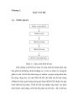
- C h a p te r 2 TENSION M EM BERS 1. TYPE OF THNSION MEMBERS Tension members are encoưntered in most Steel structures. They occur as principal structural members in bridge and roof truss, in truss structures such as transmission towers and in wind bracing systems in buildings. They írequentlv appear as secondary m em bers, being used for example as tie rods to stiffen trussed systems. The simplest tension members are made of wire rope or cable. round and square bars, and rectangular bars or plate. In buildings, wire rope, rods and bars are used pnncípally in bracing systems and sag rods for purlins in sloping roofs. Single shapes, such as angle, the plate, the w and s shapes, may be used as tension members. When the capacity of a siinple rolled xection is not sufficient, builĩ-up members are required. (two or moĩc §.hape§ Mt combined with connections). The cross- section of some íypical tension members are shown in Fíg. 2-1 • — L _ J L _ — Round bar Flat bar AngleDouibleangile Starred angle Channel Double channel Latticed channels wSiectiion s - section (W'ide -Aainge) (American Standard) Built - up box sections F ig . 2.1 Cross- S( rlio n «■/ ỉy p ic a l n lỉM cn íỉ'ici fìh e r s 109
- II. NET AREA AND EFFECTIVE AREA. 2.1. Net area W henever a tension mem ber has holes for connection (bolts, rivets), the cross-section at the connection is reduced. The area of the section deducted the areas of the holes is called net area. It will be used in the calculation of the m em ber capacity. W hen the holes are lined up transverse to the loading direction (Fig. 2-2,a), ứ.e net area An is determined by : A„ = A g - n j d t (2-1) where A g = gross area, t = thickness of the plate, d = diam eter of the hole, !1 | = num ber of holes in a line. If the íasteners are staggered (not lined up transverse to the loading direction), (Fig, 2-2,b), many ĩailure paths may occur : or on sections norm al to the axis of the memlber (section AB), or on zigzag sections (line AC). The controlling failure line is that vhiicli gives the minimum net area. To account the effect of the zigzags in failure path., a sim p lified em p irical m eth od is adopted : the net area o f the z ig z a g se c tio n is obtained by deducting from the gross area of the section all the areas lost by the holes in the fá lu re path and adding the quantity (s2/4g)t for each zigzag : An = Ag - ndt + 2 .2 ) Vv4g where n = the num ber of holes in the zigzag line ; s = the staggered pitch, or spacing of adjacent holes parallel to the loading ; g = the gage, distance between longitudinal hole lines. In the two formulas above, d is the diam eter of the hole to be deducted in calculaion. The Standard hole is 1/16 in. (1.6 mm) larger than the diam eter of the fastener. Biut according to AISC Spec., the vvidth to be dedưcted is to be taken as the nonimal dim ension of the hole plus 1/16 in. (that means, for Standard holes, this is the fastnier diam eter plus 1/8 in. or 3.2 mm). This is for accounting the damage at the edge o' tlhe hole caused by punching or drilling operation. 110
- Fig. 2-2 Determining the Iiet area 2.2. EíTective net a re a The design of tension m em bers is based on the assumption that stress is distributed over the cross section. In fact, there vviĩl be nonuniíorm distrìbutions at the holes or near the edge of the section which is far from the loading line. The ữacture may occur by a localized yielding on a effective area. The stresses are assumed to be uniíormly distributed only over this effective area. The effective area for bolted and riveted connections is given by : Ae = U A n (2-3) and for vvelđed connections by Ae = UAg (2-4) where A g = gross area, An = net area, u = efficiency íactor V alues of u are as follows : - For w , M, or s shapes with íỉange widths not less than tvvo-thirds the depth, connected by the ílanges, with welds or bolted and riveted connections with at least tliree íasteners per line in the direction of the stress, u = 0.90 ' For w , M, or s shapes not m eeting the conditions specified above, and for all other shapes including built-up sections, with welds or bolted and riveted connections wịth at least three fasteners per ỉine in the direction of the stress, u = 0.85 - For all mem bers with bolted and riveted connections with only two fasteners per li ne in the direction of the stress, u = 0.75 - If alỉ the elem ents of a m em ber cross section are connected, u = 1. ĩf the load is transm itted by transverse welđs to some but not all of the cross-sectional elem ents, Ae is taken to be the area of the direcíly connected element. 111
- m . ALLOWABLE STRESS AND DESIGN OF TENSION MEMBERS In a tension member, failure may occur by the yielding of the gross section away from the holes or by the rupture of the net effective section at the connection. The nominaỉ strength of the gross section may be expressed as : Tn = FỵA g Tn divided by a FS must not lesser than the Service load T : FyA y g
- Since the connection is welded, the net area equals the gross area. For this connection, the value u is 0.85. Thereíore T = 14.9 X Ag T = 20.0 X 0.85 X A g = 17 X Ag The required gross area of an angle is the g reater: ^ . Ễ “ í í « = 20.15«®». 2 2 The angle is to be chosen from the angle tables, for exam ple from AISC Manuai or from Vietnam ese Standard TCVN1656-75. Exam ple 2.2 Determ ine the tensile capacity of a bar from a 180x110x10 angle, connected by two rows of bolts M20 in the long leg and one row in the short leg (Fig.2-3). Standard holes are used. Steel A572, grade 50. iii Í Ầ ĩ" r iT 3 1 T ‘T p r 1 -1 I I bl 120 t r r r f m rJ-ừ-Lp---------- ----------- r p ------------ r r J i---------------------------------- i . ------- 280 - 4 : 4 '- : J_ • I” 4 ! I dị I el 65 Fig. 2-3. Exampìe 2-2 The hole diam eter to be deducted is 20 + (1/8 in.) = 23 mm For the purpose of computing the cross-sectionals area, the width of the angle and the distances betvveen gage lines must be measured along the m idthickness line of the cross section (as if we flatten the two the angle legs in a plane). The width of the angle is the sum of the widths of the two legs less their thickness, or 180 + 110 - 10 = 280 mm. The distance between the gage lines in the two legs is 65 + 65 - 1 0 = 120 mm. The net area of the section àbcde : 6.5 6.5 (28 X l)-(3 X 2.3)1 + 1 = 23.39 cm' (4 x7.5) (4x12) 113
- The net area of the section abde : (28 X 1) - 2 X 2.3 X 1 = 23.3 cm 2, which govems An = 23.3 cm 2 ; Ae = 0.85 X 23.3 = 19.8 cm 2 Steel A572 grade 50 has Fy = 50 ksi = 34.5 kN/cm 2 ; Fu = 65 ksi = 44.8 kN/cm 2 ; Aliowable stresses : Ft = 0.6 X 34.5 = 20.7 kN /cm 2 on gross area Ft = 0.5 X 44.8 = 22.4 kN/cm2 on effective net area The smaller of the two allowable loads is the tensile capacity : T = 20.7 X 28.3 = 586 kN (28.3 cm is the true gross section area of an angle) T = 22.4 X 19.9 = 446 kN, this is the tensile capacity of the bar. IV. TENSION RODS A common and simple tension member is the threaded rod. Such rods are usually secondary members, sưch as sag rods to support purlins in sloping roof, hangers to support a beam, tie rod to resist the thrust of an arch. The allowable of threaded rod is Ft = 0.33 Fu (2-7) based on the gross area using the major thread diameter. (The m ajor diam eter is that measured to the outer projections of the threads. In Standard dim ensions for threaded lasteners, usually is given the gross area). So, for Steel A36 : Ft = 19.1 ksi = 13.3 kN/cm2 for Steel A572 (grade 50) : Fị = 21.5 ksi = 14.8 kN /cm 2 Exam ple 2.3 Design sag rods to support the purlins of a 26.5° sloping roof, with aslope length cf 7.5 m. Sag rods are spaced at 1/3 points between roof trusses, which are spaced 7.2 m apart. Live load on roof : 0.57 kN/m2 of horizontaI projection. Use A36 Steel. a) Load. Rooíìng from corrugated sheet = 0 .1 5 kN /m 2 Purlin weight given = 0.18 kN /m 2 Live load, converted to distrìbuted on roof area = 0.57cos 26.5 = 0.51 kN/rrr Total 0.84 kN /m 2 . 114
- b) Sag rod force Sag rod carries only the component parallel to the roof. The tributary surface is (7.2/3) X 7.5 = 18 m 2. Load carried by One sag rod : T = 0.84 X sin 26.5 X 18 = 6.75 kN. c) Select rod diam eter : Allowable stress : Fj = 19.1 ksi = 13.3 kN /cm 2 Ó 75 Required gross area : Au = — —7 = 0.507 cm 2. g 13.3 D iam eter greater than d = v 4A / tí = 0-8 cm, should be chosen from Standard Tabỉe for threaded rod. Use 10 mm. 115
- C h ap ter 3 COLUMNS AND COMPRESSION MEMBERS I. RECALL ON THE BUCKLING OF COMPRESSION MEMBERS L et’s consider a pin-ended compression member under a axial load. W hen the load p attain a value called critical, the member becomes unstable i.e. it may begin to bend. This phenomena is called thè buckling, or lost of stability or longitudinalỊìexìon of the member. The critical load is given by the Euler formula : where I is the moment of inertia of the member cross section and E the elastic modulus. Dividing two members of the equation by the section area A, one obtains the critical stress: (3-2) where r =yJ(Ị/A) , the radius of gyration of the m em ber cross section. 1/r is the slendemess ratio of the member. These form ulas are valid only Ịp when the stress-stràin curve is a linear until a yield plateau is reached. If the critical stress [t exceeds the proportional limit, \ one uses the Engesser formula, \ in which, the Young modulus E —*• sỊ is replaced by the tangent 1 modulus Et (given by the slope Ị of the tangent to the stress-strain / curve at this point). Thus, e the critical stress of inelastic Fig. 3-1 buckling. 116
- One m ay obtain a curve of critical stress vs slendemess ratio as shown in Fig. 3-2. where there is a juncture of the Euler elastic buckling curve (a hyperbola) and the inelastic buckling curve determined experimentally after formula 3-3. But, in Steel column, there exist alvvays residual stresses due to the nonuniform cooling after rolling. The residual stresses reduce significantly the column strength. The AISC spec. uses the research results of the Structural Stability Research Council (SSCR) which proposed a parabola beginning with a vertex at Fcr = Fy where 1/r = 0 and terminating at the point Fcr = Fy/2 where it intersects and is tangent to the Euler hyperbola (Fig.3-3). The equation of this parabola is 1- (3-4) 4n2E or r ,, \2 1/r 1 - i (3-4a) 2Vcc / by replacing Cc = %Ậ2EI¥y ) . Cc is the value of i/r corresponding to the maximum elastic critical stress Fcr = 0.5Fy. Fig. 3-3 II. EFFECTIVE LENGTH OF THE COLUMN These above formulas are established for a pin-ended member. If the ends are othervvay fi;xed, the íormulas are still available provided the real length 1 is replaced by the effecĩi\"e length Kl, with K the effective-ỉength íactor. For simple situatịons as shown on Fỉ'ig. 3-4, the value KI are established theoretically. 117
- ịp . ll’ l p” Mu,ư/ 7 V KL = 0.7L KL = L KL = Ư2 Ặ ịp H t p. a) End rotations b) End rotations c) One end restrained unresừained fully restrained other unrestrained Fig. 3-4 Effective lengthsỷor some simple cases One may use the value of K in this table, taken from SSRC Guide (Table C-C2.1 Spec.) If a colum n is a part of a ữam e, its ends are partially restrained, the effective length is reduced and should be defined in each case. This problem vvill be treated afterwards. (a) (b) (c) (d) (e) (0 t i , L i i * I 1 * T /l 1 /| Ỷ ĩ □ 1-1 o / p □ í Buckked shape / ' / 1 of column Ị 1 shown by ỉ1 1 1! dashed úne 1 1 1 1 v 1 \ 1 \ 1 \| xj 1 '1 w \\w 1 \\\w \\\\\\ Ẳ t i t Theoretical K value 0 .5 0 .7 1.0 1.0 2.0 2.0 Recom mended desigh vaiues when ideal conditions are approximated 0 .6 5 0.8 1.0 1.2 2.10 2.0 Rotation fixed, Transtation fixeđ ỵ Rotation free, Transtation fixed End conditions code l-p Rotation fixed, Transtation free ĩ Rotation free, Transtation free 118
- III. ASD DESIGN OF AXIAL COMPRESSION MEMBER The basic strength curve of SSRC di\'ided by a íactor of safety is used as the allowable stress equation for slendemess ratios where inelastic buckling Controls (when K l/r < Cc) . The allowabỉe stress on gross section under vvorking load, vvhen K l/r < Cc is : (Kl/r)-,2 ” 1- 2C; Fa = (3-5) FS FS = factor of safety, depending on the slendemess ratio. For very short members, the initial curvature or load eccentricity are negligible, FS is taken equal 1.67, as for tension members. The larger the slenđem ess ratio, the greater the effects of accidental load eccentricity and initial curvaiure, AISC prescribed and increasing FS to a maximum of 15% over the basic v a lu e , i.e. 1.92. From the value FS = 1.67 for K l/r = 0 to FS = 1.92 for Kl/r = Cc. a cubic equation is used to obtain a smooth transition : ĩ s _ 5 | 3 Kl/r 1 (Kl/r) (3-6) 8 8 Cc 8 2Cl The complete formula of the allowable stress is (íorrnula E2- ] o f Spec.) : (Kl/r)- 1- F, 2CĨ Fa = (3-7) 5 3 Kl/r 1 (Kl/rj- 8 + 8 Cc 8 cỉ For m em ber with slendemess ratio exceeding Cc, elastic buckling Controls strength, according to (3-2). The FS according to (3-6), for Kl/r = Cc„ equals : FS = 23/12. The allovvable stress is given by (íormula E2-2 of Spec.): 12ti2E F, = (3-8) 23(Kl/r) The safety requirement for axially loaded member, the llocal stability of which is ensured, may be stated : fa < Fa (3-9) where : f = working load compression stress, ì"a = P/Ag, 119
- p = vvorking load axial compíession force, Y Ag = gross cross-section area of the member. For the proper work of a com pression member, the slendem ess ratio preíerably should not exceed 200. To íacilite the calculation, AISC M anual gives X tables C-36 and C-50 : Allowable Stress for com pression m em ber of 36 and 50 Speciíied Yield Stress Steel . They are calculate from AISC Spec. Equations (E2-1) and (E2-2). co Exam ple 3.1 Check the section of a colum n of 150 A572 (50) Steel for supporting a load of p = 400 kN. The colum n is 18.2 m long. Assum e that K = 1 in the direction of axe x-x and it has many supports in the dữection of axe y-y so that the eữective length Kly = 3m. The section is given in the following drawing. Steel properties : Fy = 50 ksi = 34.5 kN /cm 2 E = 29000 ksi = 20000 kN /cm 2 Section properties : A=2 X 15 X 0.8 + 40 X 0.6 = 48 cm 2 Ix = 2 X (15 X 0.8x20.42 )+ --:ỏ = 13187cm4 12 0 .8 X 1 5 3 _ 4 Iy = 2x -----—----- = 4 50 cm 12 rx = 18.2 cm ; ry = 3.35 cm KI K lv — = 100 ; — ^ = 89.5 r.y The slendem ess ratio K l/ rx = 100 will control. 2 X n2 X 20000 c° V 34.5 Suppose that the local stability is assured. Form ula (3 -6 ): 8 + 8 107 8 U 0 7 ,, 120
- W orking stress : fa = 400/40 = 10.0 kN/cm2 < Fa The section is OK. IV. LOCAL BƯCKLING The com ponents such as flanges, web which are combinied to form a column may develop wave formations when they are compressed. This is called local buckling. The critical stress of plates in compression is given by the íormula : F = k _____Ể L ____ cr 12(1 —ja2)(b/t)2 where k is a constant depending on type of stress, edge coniditions and length to width ratio ; Ịi is Poisson’s ratio, and b/t is width-to-thickness ratio. The basic provisions of AISC require the critical buckling stress of a plate not to be less than the yield stress of this plate. In other worđs, pẫate buckling is prevented prior to achieving a stress Fy, by application of design limits on wi
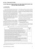
- Table C-36: Allowable Stress For Compression Members of 36-ksi Specified Yield Stress Steel KI Fa KI Fa KI F„ KI Fa KI Fa r (ksi) r (ksi) r (ksi) r (ksi) r (ksi) 1 21.56 41 19.11 81 15.24 121 10,14 161 5.76 2 21.52 42 19.03 82 15.13 122 9.99 162 5.69 3 21.48 43 18.95 83 15.02 123 9.85 163 5.62 4 21.44 44 18.86 84 14.90 124 9.70 164 5.55 5 21.39 45 18.78 85 14.79 125 9.55 165 5.49 6 21.35 46 18.70 86 14.67 126 9.41 166 5.42 7 21.30 47 18.61 87 14.56 127 9.26 167 5.35 8 21.25 48 18.53 88 14.44 128 9.11 168 5.29 9 21.21 49 18.44 89 14.32 129 8.97 169 5.23 10 21.16 50 18.35 90 14.20 130 8.84 170 5.17 11 21.10 51 18.26 91 14.09 131 8.70 171 5,11 12 21.05 52 18.17 92 13.97 132 8.57 172 5.05 13 21.00 53 18.08 93 13.84 133 8.44 173 4.99 14 20.95 54 17.99 94 13.72 134 8.32 174 4.93 15 20.89 55 17.90 95 1.1.60 135 8.19 175 4.88 16 20.83 56 17.81 96 13.48 1.75 8.07 176 4.82 17 20.78 57 17.71 97 13.35 137 7.96 177 4.77 18 20.72 58 17.62 98 13.23 138 7.84 178 4.71 19 20.66 59 17.53 99 13.10 139 7.73 179 4.66 20 20.60 60 17.43 100 12.98 140 7.62 180 4.61 21 20.54 61 17.33 101 12.85 141 7.51 181 4.56 22 20.48 62 17.24 102 12.72 142 7.41 182 4.51 23 20.41 63 17.14 103 12.59 143 7.30 183 4.46 24 20.35 64 17.04 104 12.47 144 7.20 184 4.41 25 20.28 65 16.94 105 12.33 145 7.10 165 4.36 26 20.22 66 16.84 106 12.20 146 7.01 186 4.32 27 20.15 67 16.74 107 12.07 1147 6.91 167 4.27 28 20.08 68 16.64 108 11.94 148 6.82 188 4.23 29 2.0.01 69 16.53 109 11.81 149 6.73 189 4.18 30 19.94 70 16.43 110 11.67 150 6.64 190 4.14 31 19.87 71 16.33 111 11.54 151 6.55 191 4.09 32 19.80 72 16.22 112 11.40 152 6.46 192 4.05 33 19.73 73 16,12 113 11.26 153 6.38 193 4.01 34 19.65 74 16.01 114 11.13 154 6.30 194 3,97 35 19.58 75 15.90 115 10.99 155 6.22 195 3.93 36 19.50 76 15.79 116 10.85 156 6.14 196 3.89 37 19.42 77 15.69 117 10.71 157 6.06 197 3.85 38 19.35 78 15.58 118 10.57 158 5.98 198 3.81 39 19.27 79 15.47 119 10.43 159 5.91 199 3.77 40 19.19 80 15.36 120 10.28 160 5.83 200 3.73 /Vơ/e: Cc - 126.1 122
- Table C-50: Allovvable Stress For Compression Members of 50-ks;i Specified Yield Stress Steel KI Fa KI Fa KI F* KI Fa KI Fa r (ksi) r (ksi) r (k.si) r (ksi) r (ksi) 1 29.94 41 25.69 81 18.81 121 10.20 161 5.76 2 29.87 42 25.55 82 18.61 122 10.03 162 5.69 3 29.80 43 25.40 83 18.41 123 9.87 163 5.62 4 29.73 44 25.26 84 18.20 124 9.71 164 5.55 5 29.66 45 25.11 85 17 99 125 9.56 165 5.49 6 29.58 46 24.96 86 17.79 126 9.41 166 5.42 7 29.50 47 24.81 87 17.58 127 9.26 167 5.35 8 29.42 48 24.66 88 17.37 128 9.11 168 5.29 9 29.34 49 24.51 89 17.15 129 8.97 169 5.23 10 29.26 50 24.35 90 16.94 130 8.84 170 5.17 11 29.17 51 24.19 91 16.72 131 8.70 171 5.11 12 29.08 52 24.04 92 16.50 132 8.57 172 5.05 13 28.99 53 23.88 93 16.29 133 8.44 173 4.99 14 28.90 54 23.72 94 16.06 134 8.32 174 4.93 15 28.80 55 23.55 95 15.84 135 8.19 175 4.88 16 28.71 56 23.39 96 15.62 136 8.07 176 4.82 17 28.61 57 23 22 97 15:39 137 7.96 177 4.77 18 28.51 58 23.06 98 15.17 138 7.84 178 4.71 19 28.40 59 22.89 99 14.94 139 7.73 179 4.66 20 28.30 60 22.72 100 14.71 140 762 180 4.61 21 28.19 61 22.55 10] 14.47 1141 7.51 181 4.56 22 28.08 62 6.2.37 102 14.24 142 7.41 182 4.51 23 27.97 63 22.20 103 14.00 143 7.30 183 4.46 24 27.86 64 22.02 104 13.77 144 7.20 184 4.41 25 27.75 65 21.85 105 13.53 145 7.10 185 4.36 26 27.63 66 21.67 106 13.29 146 7.01 186 4.32 27 27.52 67 21.49 107 13.04 147 6.91 187 4.27 28 27.40 68 21.31 108 12.80 148 6.82 188 4.23 29 27.28 69 21.12 109 12.57 149 6.73 189 4.18 30 27.15 70 20.94 110 12.34 150 6.64 190 4.14 31 27.03 71 20.75 111 12.12 151 6.55 191 4.09 32 26.90 72 20.56 112 11.90 152 6.46 192 4.05 33 26.77 73 20.38 113 11.69 153 6.38 193 4.01 34 26.64 74 20.10 114 11.49 154 6.30 194 3.97 35 26.51 75 19.99 115 11.29 155 6.22 195 3.93 36 26.38 76 19.80 116 11.10 156 6.14 196 3.89 37 26.25 77 19.61 117 10.91 157 6.06 197 3.85 38 26.11 78 19.41 118 10.72 158 5.98 198 3.81 39 25.97 79 19.21 119 10.55 159 5.91 199 3.77 40 25.83 80 19.01 120 10.37 160 5.83 200 3.73 Note: Q. = 107.0 123
- b) For webs in axial compression, the limiting values of noncompact section are : h 253 — < (3-12) w In the above exam ple 3-1, the section has : b _ 15/2 95 95 = 9.37 less than r -ì = 13.44; t " 0.8 1 Ji im J tụ K ~ j5 0 n .O kc = 1.0 since — = = 66.7 < 70. t 0.6 h 2.53 But — = 70 > ự = = 35.8, exceeding the noncom pact lim iting value, so the section is slender. The result of Ex. 3-1 is not right. For axial loaded members containing elem ents which have a the width-to-thickness ratio in excess of the lim iting noncompact value, the design shall be as follows : a) Flanges : The allowable stress of a slender ílange shall be sub]ect to a reduction íactor Qs. The value of Qs shall be determ ined by equations (3-13) or (3-14) as applicable, where b is half of the full nom inal width. 95 b 195 When < —< ‘ < J Ụ k : Q , = 1.293 - 0 .00309— (3-13) b 195 W hen —> t Fy / k c (3-14) b) W ebs : a reduced effective width he shall be used in com puting the design properties of the section. For webs of I section : 253t 44.3 1 (3-15) (b/t)Vf For webs and flanges of rectangular tube sections : 253t 50.3 (3-15a) he Vf (b/t)Vf 124
- In these formulas, f is the computed compressive stress in the web, based on the gross sectional area of the actual section : f = P/Ag . As prescribed in the Spec., the gross cross-sectional area and the radius of gyration shall be computed on the basis of actual cross section. But the strength of the column will be reduced by the factor Qa = effective' area / actual area The allowable stress for columns containing of slender ílanges and slender webs : (Kl/r)2 1 2C; Fa = (3-16) 5 3 (Kl/r) 1 (Kl/r)- 8 8 Cr 8 cl vvhen Kl/r is less than ơ c , where C'c = ^27C2E/QF} and Q =QA W hen Kl/r is less than ơ c : 12tt2E (3-17) 23(Kl/r) Exam ple 3.2 Check the section of a column of m A572 (50) Steel for supporting a load of p = 275 kN. The column has KI = 240 cm in both direcúon. The section is given in the following drawing. Steel properties : Fy = 50 ksi = 34.5 kN/cm2 E = 29000 ksi = 20000 kN/cm2 Gross section properties : 100 A = 2 X 10 X 0.5 + 24 X 0.5 = 22 cm 2 Ix = 2 X (1 0 X 0.5 X 1 2 .2 5 2 ) + 0 .5 X = 2077crn 12 T 0.5 X 9.753 _ ooi _4 Iv = 2 X ------------------ :------ = 331 cm y 12 y = 3.88 cm KI y- =61. 9 125
- Check the local buckling For ĩlanges : — = — = 19 and k = 1 since — = = 48 < 70 t 5 95 _ 95 = 13.4 < 19 and y Ị Ụ K ~ >Ỉ5Õ 195 _ 195 = 27.6 > 19 ~ V5Õ Reduction factor Qs = 1.293 - 0.00309 X 19 V 5 Õ = 0.878 253 _ 253 For web = 48 > = 35.8 Effective width of web 253x 0.5t 44.3 h, = = 23.2cm < h = 24cm V Ĩ8.13 48V1B.13 Effective area : A„ = 2 X 10 X 0.5 + 23.2 X 0.5 = 21.6 cm ‘ 21.6 Reduction factor Q, = = 0.988 22 Total reduction factor Q = Qs X Qa = 0.878 X 0.98 = 0.862 , _ \ J ( 2 x n 2 X 29000) Kỉ = I 15 > (0.862x34.5) / 61.9V 0 .8 6 2 x 5 0 1 - - 2 V 1 15 y 36.86 F„ = = I9.9ksi 5 3 61.9 1/ 6 1 .9 n3 1.849 8 8 115 8 15 f = 18.13 ksi < F,, the section is OK 126
- Chapter 4 BEAMS AND FLEXƯRAL M EM BERS I. BEHAVIOR OF A BEAM UNDER LOAD A beam is considered to be any member subjected principally to transverse loading, w hich involve a bending moment. So, a beam is a com bination of a tension element and a com pression element. In general, the compression elem ent (one flange) is braced perpendicular to the plane of the web to avoid the overall buckling. In this case, the beam is said as ìaterally supported. L e t’s consider I beam subjected to increasing moment. The stress distribution is shown on Fig. 4-1. At the bendíng moment in the Service load range, the section ÌS eíastic (Fig. a). The maximal stress at the extreme fiber is computed as f=— (4-1) s* w here s is the seclion modulus, deiìned as the moment of inertia I divided by the d is ta n c e from the cen ter of gravity to the ex trem e fiber (T he su bscript X indicates axis X about w hich the moment of inertia is computed). The elastic condition exists until the stress at the extrem e fiber reaches the yield stress Fy (Fig.b). The nominal mơment strength is reíerred to as the ỵìeld moment M y and is computed as My = SxFy (4-2) After, increasing strain in extreme fibers induces no ịncrease in stress (Fig.c). The section is in elastic-plastic range. When every fiber has reached the yield stress (Fíg.d), the w h o lc section is in the plastic range. The nòminal mom ent strength is referred to as the plastic moment Mp and is computed as Mp = Fy |y d A = Fy Z (4-3) where z = JydA mav be called the pìasĩic modaỉas. One may note thai z is equal to iw ice o f the static moment of the half section about axis X. O nce the plastic inoment strength has been reached, the section can offer no additional resistance to rotaíion. It behaves as a hinge but with constant resistance Mp, w h ich is k n o w n as a plastic hinge. A plastic h in ge w ill m ake a sta tica lly determ in ate be am collapse. 127
- Entirely plastic M = Mn d) Fig 4-1 The ratio £, = Mp/My, shows how bigger the m om ent capacity com puted in plastic range in com parison with the ordinary one com puted in elastic range : E=Mp = z (4-4) My s This ratio is independent of the m aterial property. It is a property of the cross section shape and is called the shape íactor. Shape factors ẽ, of some cross sections are the following : Rectangular : 1.5 ; circular : 1.7 ; w shape : 1.10 to 1.18 ; thin walled rectangular tube : 1.12. The values of section modulus s and z for Standard shapes are given in Tables (for ex. in AISC M anuals). II. ALLOWABLE STRESS DESIGN OF LATERALLY SUPPORTED BEAMS As said above, a beam is laterally supported when there exist laĩeral support (such as concrete floor slab, cross bracing at intervals) on its compression ílange to restraint its overall buckỉing out of its plane. The safety requirem ent o f a beam is as follows : M < FS where M = Service load bending moment, M n = nom inal moment strength , FS = saíety íactor in beam design, taken equal 1.67. Or in stress format, by dividing both sides by the section modulus s: fb = M < F (4-5) b s b (FS)S 128
CÓ THỂ BẠN MUỐN DOWNLOAD

-

Kỹ thuật thiết kế kết cấu thép theo TCXDVN 338:2005
 219 p |
  681
|
681
|  315
315
-

Chỉ dẫn kỹ thuật thiết kế đường
 679 p | 321
| 96
679 p | 321
| 96
-

Giáo trình Kỹ thuật thiết kế tàu
119 p | 246
| 82
-
Phân tích và lựa chọn thuật toán thiết kế kết cấu tàu vỏ thép theo yêu cầu của Quy phạm Việt Nam, chương 1
6 p | 279
| 78
-

Kỹ thuật thiết kế kết cấu nhà cao tầng bêtông cốt thép chịu động đất theo TCXDVN 375:2006: Phần 1
71 p | 243
| 64
-

Kỹ thuật thiết kế kết cấu nhà cao tầng bêtông cốt thép chịu động đất theo TCXDVN 375:2006: Phần 2
80 p | 220
| 50
-

Phân tích và lựa chọn thuật toán thiết kế kết cấu tàu vỏ thép theo yêu cầu của Quy phạm Việt Nam, chương 3
8 p | 213
| 45
-

Phân tích và lựa chọn thuật toán thiết kế kết cấu tàu vỏ thép theo yêu cầu của Quy phạm Việt Nam, chương 5
7 p | 192
| 39
-

Phân tích và lựa chọn thuật toán thiết kế kết cấu tàu vỏ thép theo yêu cầu của Quy phạm Việt Nam, chương 9
9 p | 170
| 34
-
Phân tích và lựa chọn thuật toán thiết kế kết cấu tàu vỏ thép theo yêu cầu của Quy phạm Việt Nam, chương 6
13 p | 164
| 34
-

Tính toán các kết cấu mặt đường và Hướng dẫn kỹ thuật thiết kế: Phần 2
105 p | 167
| 24
-

Phân tích và lựa chọn thuật toán thiết kế kết cấu tàu vỏ thép theo yêu cầu của Quy phạm Việt Nam, chương 15
5 p | 158
| 24
-

Sổ tay thiết kế kết cấu cọc ván thép: Phần 2
147 p | 26
| 11
-
Hệ số tầm quan trọng trong các tiêu chuẩn thiết kế kết cấu của Việt Nam và nước ngoài
6 p | 176
| 6
-

Giáo trình Ứng dụng Sap trong thiết kế kết cấu (Nghề: Kỹ thuật xây dựng - Trình độ CĐ/TC) - Trường Cao đẳng Nghề An Giang
61 p | 13
| 3
-

Một số nội dung quan trọng trong dự thảo tiêu chuẩn cơ sở thiết kế kết cấu theo định hướng mới
9 p | 37
| 2
-

Kỹ thuật thiết kế công trình cống và cầu nhỏ trên đường ôtô: Phần 2
162 p | 2
| 1
-

Thiết kế kết cấu bê tông và bê tông cốt thép: Phần 1
262 p | 1
| 1


Chịu trách nhiệm nội dung:
Nguyễn Công Hà - Giám đốc Công ty TNHH TÀI LIỆU TRỰC TUYẾN VI NA
LIÊN HỆ
Địa chỉ: P402, 54A Nơ Trang Long, Phường 14, Q.Bình Thạnh, TP.HCM
Hotline: 093 303 0098
Email: support@tailieu.vn
Giấy phép Mạng Xã Hội số: 670/GP-BTTTT cấp ngày 30/11/2015 Copyright © 2022-2032 TaiLieu.VN. All rights reserved.

