


Windows Internals covering windows server 2008 and windows vista- P13
lượt xem 8
download
 Download
Vui lòng tải xuống để xem tài liệu đầy đủ
Download
Vui lòng tải xuống để xem tài liệu đầy đủ
Windows Internals covering windows server 2008 and windows vista- P13: In this chapter, we’ll introduce the key Microsoft Windows operating system concepts and terms we’ll be using throughout this book, such as the Windows API, processes, threads, virtual memory, kernel mode and user mode, objects, handles, security, and the registry.
Bình luận(0) Đăng nhập để gửi bình luận!
Nội dung Text: Windows Internals covering windows server 2008 and windows vista- P13
- I/O system objects, including driver and device objects. Internally, the Windows I/O system operates asynchronously to achieve high performance and provides both synchronous and asynchronous I/O capabilities to user-mode applications. Device drivers include not only traditional hardware device drivers but also file system, network, and layered filter drivers. All drivers have a common structure and communicate with one another and the I/O manager by using common mechanisms. The I/O system interfaces allow drivers to be written in a high-level language to lessen development time and to enhance their portability. Because drivers present a common structure to the operating system, they can be layered one on top of another to achieve modularity and reduce duplication between drivers. Also, all Windows device drivers should be designed to work correctly on multiprocessor systems. Finally, the role of the PnP manager is to work with device drivers to dynamically detect hardware devices and to build an internal device tree that guides hardware device enumeration and driver installation. The power manager works with device drivers to move devices into low-power states when applicable to conserve energy and prolong battery life. Four more upcoming chapters in the book will cover additional topics related to the I/O system: storage management, file systems (including details on the NTFS file system), the cache manager, and networking. 590 Please purchase PDF Split-Merge on www.verypdf.com to remove this watermark.
- 8. Storage Management Storage management defines the way that an operating system interfaces with nonvolatile storage devices and media. The term storage encompasses many different devices, including tape drives, optical media, USB flash drives, floppy disks, hard disks, network storage such as iSCSI, and storage area networks (SANs). Windows provides specialized support for each of these classes of storage media. Because our focus in this book is on the kernel components of Windows, in this chapter we’ll concentrate on just the fundamentals of the hard-disk storage subsystem in Windows, which includes support for external disks and flash drives. Significant portions of the support Windows provides for removable media and remote storage (offline archiving) are implemented in user mode. In this chapter, we’ll examine how kernel-mode device drivers interface file system drivers to disk media, discuss how disks are partitioned, describe the way volume managers abstract and manage volumes, and present the implementation of multipartition disk-management features in Windows, including replicating and dividing file system data across physical disks for reliability and for performance enhancement. We’ll also describe how file system drivers mount volumes they are responsible for managing, and we’ll conclude by discussing drive encryption technology in Windows and support for automatic backups and recovery. 8.1 Storage Terminology To fully understand the rest of this chapter, you need to be familiar with some basic terminology: ■ Disks are physical storage devices such as a hard disk, a 3.5-inch floppy disk, or a CD-ROM. ■ A disk is divided into sectors, which are addressable blocks of fixed size. Sector sizes are determined by hardware. Most hard disk sectors are 512 bytes, and CD-ROM sectors are typically 2048 bytes. ■ Partitions are collections of contiguous sectors on a disk. A partition table or other diskmanagement database stores a partition’s starting sector, size, and other characteristics and is located on the same disk as the partition. ■ Simple volumes are objects that represent sectors from a single partition that file system drivers manage as a single unit. ■ Multipartition volumes are objects that represent sectors from multiple partitions and that file system drivers manage as a single unit. Multipartition volumes offer performance, reliability, and sizing features that simple volumes do not. 591 Please purchase PDF Split-Merge on www.verypdf.com to remove this watermark.
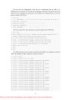
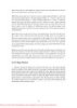
- 8.2 Disk Drivers The device drivers involved in managing a particular storage device are collectively known as a storage stack. Figure 8-1 shows each type of driver that might be present in a stack and includes a brief description of its purpose. This chapter describes the behavior of device drivers below the file system layer in the stack. (The file system driver operation is described in Chapter 11.) 8.2.1 Winload As you saw in Chapter 4, Winload is the Windows operating system file that conducts the first portion of the Windows boot process. Although Winload isn’t technically part of the storage stack, it is involved with storage management because it includes support for accessing disk devices before the Windows I/O system is operational. Winload resides on the boot volume; the boot-sector code on the system volume executes Bootmgr. Bootmgr reads the BCD from the system volume or EFI firmware and presents the computer’s boot choices to the user. Bootmgr translates the name of the BCD boot entry that a user selects to the appropriate boot partition and then runs Winload to load the Windows system files (starting with the registry, Ntoskrnl.exe and its dependencies, and the boot drivers) into memory to continue the boot process. In all cases, Winload uses the computer firmware to read the disk containing the system volume. 8.2.2 Disk Class, Port, and Miniport Drivers During initialization, the Windows I/O manager starts the disk storage drivers. Storage drivers in Windows follow a class/port/miniport architecture, in which Microsoft supplies a storage class driver that implements functionality common to all storage devices and a storage port driver that implements functionality common to a particular bus—such as a Small Computer System Interface (SCSI) bus or an Integrated Device Electronics (IDE) system—and OEMs supply miniport drivers that plug into the port driver to interface Windows to a particular controller implementation. In the disk storage driver architecture, only class drivers conform to the standard Windows device driver interfaces. Miniport drivers use a port driver interface instead of the device driver interface, and the port driver simply implements a collection of device driver support routines that interface miniport drivers to Windows. This approach simplifies the role of miniport driver developers and, because Microsoft supplies operating system–specific port drivers, allows driver developers to focus on hardware-specific driver logic. Windows includes Disk (\Windows\System32\Drivers \Disk.sys), a class driver that implements functionality common to disks. Windows also provides a handful of disk port drivers. For example, Scsiport.sys is the legacy port driver for disks on SCSI buses, and Ataport.sys is a port driver for IDEbased systems. Most newer drivers use the Storport.sys port driver as a replacement for Scsiport.sys. Storport.sys is designed to realize the high performance capabilities of hardware RAID and Fibre Channel adapters. The Storport model is similar to Scsiport, making it easy for vendors to migrate existing Scsiport miniport drivers to 592 Please purchase PDF Split-Merge on www.verypdf.com to remove this watermark.
- Storport. Miniport drivers that developers write to use Storport take advantage of several of Storport’s performance enhancing features, including support for the parallel execution of I/O initiation and completion on multiprocessor systems, more controllable I/O request-queue architecture, and execution of more code at lower IRQL to minimize the duration of hardware interrupt masking. Storport also includes support for dynamic redirection of interrupts and DPCs to the best (most local) NUMA node on systems that support it. Both the Scsiport.sys and Ataport.sys drivers implement a version of the disk scheduling algorithm known as C-LOOK. The drivers place disk I/O requests in lists sorted by the first sector (also known as the logical block address, or LBA) at which an I/O request is directed. They use the KeInsertByKeyDeviceQueue and KeRemoveByKeyDeviceQueue functions (documented in the Windows Driver Kit) representing I/O requests as items and using a request’s starting sector as the key required by the functions. When servicing requests, the drivers proceed through the list from lowest sector to highest. When they reach the end of the list the drivers start back at the beginning, since new requests might have been inserted in the meantime. If disk requests are spread throughout a disk this approach results in the disk head continuously moving from near the outermost cylinders of the disk toward the innermost cylinders. Storport.sys does not implement disk scheduling because it is commonly used for managing I/Os directed at storage arrays where there is no clearly defined notion of a disk start and end. Windows ships with several miniport drivers, including one—Aha154x.sys—for Adaptec’s 1540 family of SCSI controllers. On systems that have at least one ATAPI-based IDE device, Atapi.sys, Pciidex.sys, and Pciide.sys together provide miniport functionality. Most Windows installations include one or more of the drivers mentioned. iSCSI Drivers The development of iSCSI as a disk transport protocol integrates the SCSI protocol with TCP/IP networking so that computers can communicate with block-storage devices, including disks, over IP networks. Storage area networking (SAN) is usually architected on Fibre Channel networking, but administrators can leverage iSCSI to create relatively inexpensive SANs from networking technology such as Gigabit Ethernet to provide scalability, disaster protection, efficient backup, and data protection. Windows support for iSCSI comes in the form of the Microsoft iSCSI Software Initiator, which can be installed as a feature on Windows Vista Enterprise and Windows Vista Ultimate, as well as on Windows Server 2008. The Microsoft iSCSI Software Initiator includes several components: ■ Initiator This optional component, which consists of the Storport port driver and the iSCSI miniport driver (\Windows\System32\Drivers\Msiscsi.sys), uses the TCP/IP driver to implement software iSCSI over standard Ethernet adapters and TCP/IP offloaded network adapters. ■ Initiator service This service, implemented in \Windows\System32\Iscsiexe.exe, manages the discovery and security of all iSCSI initiators as well as session initiation and termination. iSCSI 593 Please purchase PDF Split-Merge on www.verypdf.com to remove this watermark.
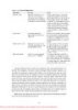
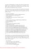
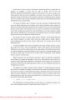
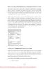
- device discovery functionality is implemented in \Windows\System32\Iscsium.dll and conforms to the Internet Storage Name Service (iSNS) protocol. ■ Management applications These include Iscsicli.exe, a command-line tool for managing iSCSI device connections and security, and the corresponding Control Panel application. Some vendors produce iSCSI adapters that offload the iSCSI protocol to hardware. The Initiator service works with these adapters, which must support iSNS, so that all iSCSI devices, including those discovered by the Initiator service and those discovered by iSCSI hardware, are recognized and managed through standard Windows interfaces. Multipath I/O (MPIO) Drivers Most disk devices have one path—or series of adapters, cables, and switches—between them and a computer. Servers requiring high levels of availability use multipathing solutions, where more than one set of connection hardware exists between the computer and a disk so that if a path fails the system can still access the disk via an alternate path. Without support from the operating system or disk drivers, however, a disk with two paths, for example, appears as two different disks. Windows includes multipath I/O support to manage multipath disks as a single disk. This support relies on built-in or third-party drivers called device-specific modules (DSMs) to manage details of the path management—for example, load balancing policies that choose which path to use for routing requests and error detection mechanisms to inform Windows when a path fails. MPIO support is available for Windows Server 2008 in the form of the Microsoft MPIO Driver Development Kit, which hardware and software vendors can license. In a Windows MPIO storage stack, shown in Figure 8-2, the disk driver includes functionality for MPIO devices. Disk.sys is responsible for claiming ownership of device objects representing multipath disks—so that it can ensure that only one device object is created to represent those disks—and for locating the appropriate DSM to manage the paths to the device. The Multipath Bus Driver (\Windows\System32\Drivers\Mpio.sys) manages connections between the computer and the device, including power management for the device. Disk.sys informs Mpio.sys of the presence of the devices for it to manage. Finally, the port driver for a multipath disk is also MPIO-aware in order to manage information passed up the device stack. There are therefore a total of three disk device stacks, two representing the physical paths (children of the adapter device stacks) and one representing the disk (child of the MPIO adapter device stack). When the latter receives a request, it uses the DSM to determine which path to forward that request to. The DSM makes the selection based on policy, and the request is sent to the corresponding disk device stack, which in turn forwards it to the device via the corresponding adapter. EXPERIMENT: Watching Physical Disk i/O Diskmon from Windows Sysinternals (www.microsoft.com/technet/sysinternals) uses the disk class driver’s Event Tracing for Windows (or ETW, which is described in Chapter 3) instrumentation to monitor I/O activity to physical disks and display it in a window. Diskmon 594 Please purchase PDF Split-Merge on www.verypdf.com to remove this watermark.
- updates once a second with new data. For each operation, Diskmon shows the time, duration, target disk number, type and offset, and length, as you can see in the screen shown here. 595 Please purchase PDF Split-Merge on www.verypdf.com to remove this watermark.
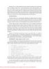
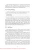
- 8.2.3 Disk Device Objects The Windows disk class driver creates device objects that represent disks. Device objects that represent disks have names of the form \Device\HarddiskX\DRX; the number that identifies the disk replaces both Xs. To maintain compatibility with applications that use older naming conventions, the disk class driver creates symbolic links with Windows NT 4–formatted names that refer to the device objects the driver created. For example, the volume manager driver creates the link \Device\Harddisk0\Partition0 to refer to \Device\Harddisk0\DR0, and \Device\Harddisk0 \Partition1 to refer to the first partition device object of the first disk. For backward compatibility with applications that expect legacy names, the disk class driver also creates the same symbolic links in Windows that represent physical drives that it would have created on Windows NT 4 systems. Thus, for example, the link \GLOBAL??\PhysicalDrive0 references \Device\Harddisk0 \DR0. Figure 8-3 shows the WinObj utility from Sysinternals displaying the contents of a Harddisk directory for a basic disk. You can see the physical disk and partition device objects in the pane at the right. As you saw in Chapter 3, the Windows API is unaware of the Windows object manager namespace. Windows reserves two groups of namespace subdirectories to use, one of which is the \Global?? subdirectory. (The other group is the collection of per-session \BaseNamed-Objects subdirectories, which are covered in Chapter 3.) In this subdirectory, Windows makes available device objects that Windows applications interact with—including COM and parallel ports—as well as disks. Because disk objects actually reside in other subdirectories, Windows uses symbolic links to connect names under \Global?? with objects located elsewhere in the namespace. For each physical disk on a system, the I/O manager creates a \Global??\ PhysicalDriveX link that points to \Device\HarddiskX\DRX. (Numbers, starting from 0, replace X.) Windows applications that directly interact with the sectors on a disk open the disk by calling the Windows CreateFile 596 Please purchase PDF Split-Merge on www.verypdf.com to remove this watermark.
- function and specifying the name \\.\PhysicalDriveX (in which X is the disk number) as a parameter. The Windows application layer converts the name to \Global??\PhysicalDriveX before handing the name to the Windows object manager. 8.2.4 Partition Manager The partition manager, \Windows\System32\Drivers\Partmgr.sys, is responsible for discovering, creating, deleting, and managing partitions. To become aware of partitions, the partition manager acts as the function driver for disk device objects created by disk class drivers. The partition manager uses the I/O manager’s IoReadPartitionTableEx function to identify partitions and create device objects that represent them. As miniport drivers present the disks that they identify early in the boot process to the disk class driver, the disk class driver invokes the IoReadPartitionTableEx function for each disk. This function invokes sector-level disk I/O that the class, port, and miniport drivers provide to read a disk’s MBR or GPT (described later in this chapter) and construct an internal representation of the disk’s partitioning. The partition manager driver creates device objects to represent each primary partition (including logical drives within extended partitions) that the driver obtains from IoRead PartitionTableEx. These names have the form \Device\HarddiskVolumeY, where Y represents the partition number. When a partition is added, a private IOCTL command is sent to each registered volume manager, asking the volume manager if it owns that partition. If so, the partition manager remembers the specific volume manager that claimed that partition, and from this point on it notifies that driver when the partition is either deleted or modified. Volume manager device drivers receive the notification of partitions for disks that they manage and define volume objects when they account for all the partitions that make up the volumes. The partition manager is also responsible for ensuring that all disks and partitions have a unique ID (signature for MBR and GUIDs for GPT). If it encounters two disks with the same ID, it tries to determine (by writing to one disk and reading from the other) whether they are two different disks or the same disk being viewed via two different paths (this can happen if the MPIO software isn’t present or isn’t working correctly). If the two disks are different, the partition manager changes the ID of one of them; if they are two paths to the same disk, the partition manager hides all the partitions on one of the disks from the volume managers to prevent the partitions from being mounted twice. By managing disk attributes that are persisted in the registry (such as read-only and offline), the partition manager can perform actions such as hiding partitions from the volume managers, which inhibits the volumes from manifesting on the system. Clustering and Hyper-V use these attributes. The partition manager also redirects write operations that are sent directly to the disk but fall within a partition space to the corresponding volume manager. The volume manager determines whether to allow the write operation based on whether the volume is dismounted or not. 597 Please purchase PDF Split-Merge on www.verypdf.com to remove this watermark.
- 8.3 Volume Management Windows has the concept of basic and dynamic disks. Windows calls disks that rely exclusively on the MBR-style or GPT partitioning scheme basic disks. Dynamic disks implement a more flexible partitioning scheme than that of basic disks. The fundamental difference between basic and dynamic disks is that dynamic disks support the creation of new multipartition volumes. Recall from the list of terms earlier in the chapter that multipartition volumes provide performance, sizing, and reliability features not supported by simple volumes. Windows manages all disks as basic disks unless you manually create dynamic disks or convert existing basic disks (with enough free space) to dynamic disks. Microsoft recommends that you use basic disks unless you require the multipartition functionality of dynamic disks. Note Windows does not support multipartition volumes on basic disks. For a number of reasons, including the fact that laptops usually have only one disk and laptop disks typically don’t move easily between computers, Windows uses only basic disks on laptops. In addition, only fixed disks can be dynamic, and disks located on IEEE 1394 or USB buses or on shared cluster server disks are always basic disks (or fixed dynamic disks). 8.3.1 Basic Disks This section describes the two types of partitioning, MBR-style and GPT, that Windows uses to define volumes on basic disks, and the volume manager driver that presents the volumes to file system drivers. Windows silently defaults to defining all disks as basic disks. MBR-Style Partitioning The standard BIOS implementations that BIOS-based (non-EFI) x86 hardware uses dictate one requirement of the partitioning format in Windows—that the first sector of the primary disk contains the Master Boot Record (MBR). When a BIOS-based x86 system boots, the computer’s BIOS reads the MBR and treats part of the MBR’s contents as executable code. The BIOS invokes the MBR code to initiate an operating system boot process after the BIOS performs preliminary configuration of the computer’s hardware. In Microsoft operating systems such as Windows, the MBR also contains a partition table. A partition table consists of four entries that define the locations of as many as four primary partitions on a disk. The partition table also records a partition’s type. Numerous predefined partition types exist, and a partition’s type specifies which file system the partition includes. For example, partition types exist for FAT32 and NTFS. A special partition type, an extended partition, contains another MBR with its own partition table. The equivalent of a primary partition in an extended partition is called a logical drive. By using extended partitions, Microsoft’s operating systems overcome the apparent limit of four partitions per disk. In general, the recursion that extended partitions permit can continue indefinitely, which means that no upper limit exists to the number of possible partitions on a disk. The Windows boot process makes evident the distinction between primary and logical drives. The system must mark 598 Please purchase PDF Split-Merge on www.verypdf.com to remove this watermark.
- one primary partition of the primary disk as active. The Windows code in the MBR loads the code stored in the first sector of the active partition (the system volume) into memory and then transfers control to that code. Because of the role in the boot process played by this first sector in the primary partition, Windows designates the first sector of any partition as the boot sector. As you will see in Chapter 13, every partition formatted with a file system has a boot sector that stores information about the structure of the file system on that partition. GUID Partition Table Partitioning As part of an initiative to provide a standardized and extensible firmware platform for operating systems to use during their boot process, Intel has designed the Extensible Firmware Interface (EFI) specification. EFI includes a mini–operating system environment implemented in firmware (typically ROM) that operating systems use early in the system boot process to load system diagnostics and their boot code. EFI defines a partitioning scheme, called the GUID (globally unique identifier) Partition Table (GPT) that addresses some of the shortcomings of MBR-style partitioning. For example, the sector addresses that the GPT structures use are 64 bits wide instead of 32 bits. A 32-bit sector address is sufficient to access only 2 terabytes (TB) of storage, while a GPT allows the addressing of disk sizes into the foreseeable future. Other advantages of the GPT scheme include the fact that it uses cyclic redundancy checksums (CRC) to ensure the integrity of the partition table, and it maintains a backup copy of the partition table. GPT takes its name from the fact that in addition to storing a 36-byte Unicode partition name for each partition, it assigns each partition a GUID. Figure 8-4 shows a sample GPT partition layout. Like for MBR-style partitioning, the first sector of a GPT disk is an MBR that serves to protect the GPT partitioning in case the disk is accessed from a non-GPT aware operating system. However, the second and last sectors of the disk store the GPT headers with the actual partition table following the second sector and preceding the last sector. With its extensible list of partitions, GPT partitioning doesn’t require nested partitions, as MBR partitions do. 599 Please purchase PDF Split-Merge on www.verypdf.com to remove this watermark.
- Note Because Windows doesn’t support the creation of multipartition volumes on basic disks, a new basic disk partition is the equivalent of a volume. For this reason, the Disk Management MMC snap-in uses the term partition when you create a volume on a basic disk. Basic Disk Volume Manager The volume manager driver (\Windows\System32\Drivers\Volmgr.sys) creates disk device objects that represent volumes on basic disks and plays an integral role in managing all basic disk volumes, including simple volumes. For each volume, the volume manager creates a device object of the form \Device\HarddiskVolumeX, in which X is a number (starting from 1) that identifies the volume. The volume manager is actually a bus driver because it’s responsible for enumerating basic disks to detect the presence of basic volumes and report them to the Windows Plug and Play (PnP) manager. To implement this enumeration, the volume manager leverages the PnP manager, with the aid of the partition manager (Partmgr.sys) driver to determine what basic disk partitions exist. The partition manager registers with the PnP manager so that Windows can inform the partition manager whenever the disk class driver creates a partition device object. The partition manager informs the volume manager about new partition objects through a private interface and creates filter device objects that the partition manager then attaches to the partition objects. The existence of the filter objects prompts Windows to inform the partition manager whenever a partition device object is deleted so that the partition manager can update the volume manager. The disk class driver deletes a partition device object when a partition in the Disk Management MMC snap-in is deleted. As the volume manager becomes aware of partitions, it uses the basic disk configuration information to determine the correspondence of partitions to volumes and creates a volume device object when it has been informed of the presence of all the partitions in a volume’s description. Windows volume drive-letter assignment, a process described shortly, creates drive-letter symbolic links under the \Global?? object manager directory that point to the volume device objects that the volume manager creates. When the system or an application accesses a volume for the first time, Windows performs a mount operation that gives file system drivers the opportunity to recognize and claim ownership for volumes formatted with a file system type they manage. (Mount operations are described in the section “Volume Mounting” later in this chapter.) 8.3.2 Dynamic Disks As we’ve stated, dynamic disks are the disk format in Windows necessary for creating multipartition volumes such as mirrors, striped arrays, and RAID-5 arrays (described later in the chapter). Dynamic disks are partitioned using Logical Disk Manager (LDM) partitioning. LDM is part of the Virtual Disk Service (VDS) subsystem in Windows, which consists of user-mode and device driver components and oversees dynamic disks. A major difference between LDM’s partitioning and MBR-style and GPT partitioning is that LDM maintains one unified database that 600 Please purchase PDF Split-Merge on www.verypdf.com to remove this watermark.
- stores partitioning information for all the dynamic disks on a system—including multipartition-volume configuration. The LDM Database The LDM database resides in a 1-MB reserved space at the end of each dynamic disk. The need for this space is the reason Windows requires free space at the end of a basic disk before you can convert it to a dynamic disk. The LDM database consists of four regions, which Figure 8-5 shows: a header sector that LDM calls the Private Header, a table of contents area, a database records area, and a transactional log area. (The fifth region shown in Figure 8-5 is simply a copy of the Private Header.) The Private Header sector resides 1 MB before the end of a dynamic disk and anchors the database. As you spend time with Windows, you’ll quickly notice that it uses GUIDs to identify just about everything, and disks are no exception. A GUID (globally unique identifier) is a 128-bit value that various components in Windows use to uniquely identify objects. LDM assigns each dynamic disk a GUID, and the Private Header sector notes the GUID of the dynamic disk on which it resides—hence the Private Header’s designation as information that is private to the disk. The Private Header also stores the name of the disk group, which is the name of the computer concatenated with Dg0 (for example, Daryl-Dg0 if the computer’s name is Daryl), and a pointer to the beginning of the database table of contents. For reliability, LDM keeps a copy of the Private Header in the disk’s last sector. The database table of contents is 16 sectors in size and contains information regarding the database’s layout. LDM begins the database record area immediately following the table of contents with a sector that serves as the database record header. This sector stores information about the database record area, including the number of records it contains, the name and GUID of the disk group the database relates to, and a sequence number identifier that LDM uses for the next entry it creates in the database. Sectors following the database record header contain 128-byte fixed-size records that store entries that describe the disk group’s partitions and volumes. A database entry can be one of four types: partition, disk, component, and volume. LDM uses the database entry types to identify three levels that describe volumes. LDM connects entries with internal object identifiers. At the lowest level, partition entries describe soft partitions, which are contiguous regions on a disk; identifiers stored in a partition entry link the entry to a component and disk entry. A disk entry represents a dynamic disk that is part of the disk group and includes the disk’s GUID. A component entry serves as a connector between one or more partition entries and the volume entry each partition is associated with. A volume entry stores the GUID of the volume, the volume’s total size and state, and a drive-letter hint. Disk entries that are larger than a database record span multiple records; partition, component, and volume entries rarely span multiple records. 601 Please purchase PDF Split-Merge on www.verypdf.com to remove this watermark.
- LDM requires three entries to describe a simple volume: a partition, component, and volume entry. The following listing shows the contents of a simple LDM database that defines one 200-MB volume that consists of one partition: The partition entry describes the area on a disk that the system assigned to the volume, the component entry connects the partition entry with the volume entry, and the volume entry contains the GUID that Windows uses internally to identify the volume. Multipartition volumes require more than three entries. For example, a striped volume (which is described later in the chapter) consists of at least two partition entries, a component entry, and a volume entry. The only volume type that has more than one component entry is a mirror; mirrors have two component entries, each of which represents one-half of the mirror. LDM uses two component entries for mirrors so that when you break a mirror, LDM can split it at the component level, creating two volumes with one component entry each. The final area of the LDM database is the transactional log area, which consists of a few sectors for storing backup database information as the information is modified. This setup safeguards the database in case of a crash or power failure because LDM can use the log to return the database to a consistent state. EXPERIMENT: using LDMDump to View the LDM Database You can use LDMDump from Sysinternals to view detailed information about the contents of the LDM database. LDMDump takes a disk number as a command-line argument, and its output is usually more than a few screens in size, so you should pipe its output to a file for viewing in a text editor—for example, ldmdump /d0 > disk.txt. The following example shows excerpts of LDMDump output. The LDM database header displays first, followed by the LDM database records that describe a 12-GB disk with three 4-GB dynamic volumes. The volume’s database entry is listed as Volume1. At the end of the output, LDMDump lists the soft partitions and definitions of volumes it locates in the database. 602 Please purchase PDF Split-Merge on www.verypdf.com to remove this watermark.
- 1. C:\>ldmdump /d0 2. Logical Disk Manager Configuration Dump v1.03 3. Copyright (C) 2000-2002 Mark Russinovich 4. PRIVATE HEAD: 5. Signature : PRIVHEAD 6. Version : 2.12 7. Disk Id : b5f4a801-758d-11dd-b7f0-000c297f0108 8. Host Id : 1b77da20-c717-11d0-a5be-00a0c91db73c 9. Disk Group Id : b5f4a7fd-758d-11dd-b7f0-000c297f0108 10. Disk Group Name : WIN-SL5V78KD01W-Dg0 11. Logical disk start : 3F 12. Logical disk size : 7FF7C1 (4094 MB) 13. Configuration start: 7FF800 14. Configuration size : 800 (1 MB) 15. Number of TOCs : 2 16. TOC size : 7FD (1022 KB) 17. Number of Configs : 1 18. Config size : 5C9 (740 KB) 19. Number of Logs : 1 20. Log size : E0 (112 KB) 21. TOC 1: 22. Signature : TOCBLOCK 23. Sequence : 0x1 24. Config bitmap start: 0x11 25. Config bitmap size : 0x5C9 26. Log bitmap start : 0x5DA 27. Log bitmap size : 0xE0 28. ... 29. VBLK DATABASE: 30. 0x000004: [000001] 31. Name : WIN-SL5V78KD01W-Dg0 32. Object Id : 0x0001 33. GUID : b5f4a7fd-758d-11dd-b7f0-000c297f010 34. 0x000006: [000003] 35. Name : Disk1 36. Object Id : 0x0002 37. Disk Id : b5f4a7fe-758d-11dd-b7f0-000c297f010 38. 0x000007: [000005] 39. Name : Disk2 40. Object Id : 0x0003 41. Disk Id : b5f4a801-758d-11dd-b7f0-000c297f010 42. 0x000008: [000007] 43. Name : Disk3 44. Object Id : 0x0004 603 Please purchase PDF Split-Merge on www.verypdf.com to remove this watermark.
- 45. Disk Id : b5f4a804-758d-11dd-b7f0-000c297f010 46. 0x000009: [000009] 47. Name : Volume1-01 48. Object Id : 0x0006 49. Parent Id : 0x0005 50. 0x00000A: [00000A] 51. Name : Disk1-01 52. Object Id : 0x0007 53. Parent Id : 0x3157 54. Disk Id : 0x0000 55. Start : 0x7C100 56. Size : 0x0 (0 MB) 57. Volume Off : 0x3 (0 MB) 58. 0x00000B: [00000B] 59. Name : Disk2-01 60. Object Id : 0x0008 61. Parent Id : 0x3157 62. Disk Id : 0x0000 63. Start : 0x7C100 64. Size : 0x0 (0 MB) 65. Volume Off : 0x7FE80003 (1047808 MB) 66. 0x00000C: [00000C] 67. Name : Disk3-01 68. Object Id : 0x0009 69. Parent Id : 0x3157 70. Disk Id : 0x0000 71. Start : 0x7C100 72. Size : 0x0 (0 MB) 73. Volume Off : 0xFFD00003 (2095616 MB) 74. 0x00000D: [00000F] 75. Name : Volume1 76. Object Id : 0x0005 77. Volume state: ACTIVE 78. Size : 0x017FB800 (12279 MB) 79. GUID : b5f4a806-758d-11dd-b7f0-c297f0108 80. Drive Hint : E: LDM and GPT or MBR-Style Partitioning When you install Windows on a computer, one of the first things it requires you to do is to create a partition on the system’s primary physical disk. Windows defines the system volume on this partition to store the files that it invokes early in the boot process. In addition, Windows Setup requires you to create a partition that serves as the home for the boot volume, onto which the setup program installs the Windows system files and creates the system directory (\Windows). The system and boot volumes can be the same volume, in which case you don’t have to create a new 604 Please purchase PDF Split-Merge on www.verypdf.com to remove this watermark.
- partition for the boot volume. The nomenclature that Microsoft defines for system and boot volumes is somewhat confusing. The system volume is where Windows places boot files, including the boot loader (Winload) and Boot Manager (Bootmgr), and the boot volume is where Windows stores operating system files such as Ntoskrnl.exe, the core kernel file. Although the partitioning data of a dynamic disk resides in the LDM database, LDM implements MBR-style partitioning or GPT partitioning so that the Windows boot code can find the system and boot volumes when the volumes are on dynamic disks. (Winload and the IA64 firmware, for example, know nothing about LDM partitioning.) If a disk contains the system or boot volumes, partitions in the MBR or GPT describe the location of those volumes. Otherwise, one partition encompasses the entire usable area of the disk. LDM marks this partition as type “LDM”. The region encompassed by this place-holding MBR-style or GPT partition is where LDM creates partitions that the LDM database organizes. On MBRpartitioned disks the LDM database resides in hidden sectors at the end of the disk, and on GPT-partitioned disks there exists an LDM metadata partition that encompasses the LDM database near the beginning of the disk. Another reason LDM creates an MBR or a GPT is so that legacy disk-management utilities, including those that run under Windows and under other operating systems in dual-boot environments, don’t mistakenly believe a dynamic disk is unpartitioned. Because LDM partitions aren’t described in the MBR or GPT of a disk, they are called soft partitions; MBR-style and GPT partitions are called hard partitions. Figure 8-6 illustrates this dynamic disk layout on an MBR-style partitioned disk. 8.3.3 Multipartition Volume Management As we’ve stated, dynamic disks are the disk format in Windows necessary for creating multipartition volumes such as mirrors, striped arrays, and RAID-5 arrays (described later in the chapter). Dynamic disks are partitioned using Logical Disk Manager (LDM) partitioning. LDM is part of the Virtual Disk Service (VDS) subsystem in Windows, which consists of user-mode and device driver components and oversees dynamic disks. A major difference between LDM’s partitioning and MBR-style and GPT partitioning is that LDM maintains one unified database that stores partitioning information for all the dynamic disks on a system—including multipartition-volume configuration. The LDM Database 605 Please purchase PDF Split-Merge on www.verypdf.com to remove this watermark.
- The LDM database resides in a 1-MB reserved space at the end of each dynamic disk. The need for this space is the reason Windows requires free space at the end of a basic disk before you can convert it to a dynamic disk. The LDM database consists of four regions, which Figure 8-5 shows: a header sector that LDM calls the Private Header, a table of contents area, a database records area, and a transactional log area. (The fifth region shown in Figure 8-5 is simply a copy of the Private Header.) The Private Header sector resides 1 MB before the end of a dynamic disk and anchors the database. As you spend time with Windows, you’ll quickly notice that it uses GUIDs to identify just about everything, and disks are no exception. A GUID (globally unique identifier) is a 128-bit value that various components in Windows use to uniquely identify objects. LDM assigns each dynamic disk a GUID, and the Private Header sector notes the GUID of the dynamic disk on which it resides—hence the Private Header’s designation as information that is private to the disk. The Private Header also stores the name of the disk group, which is the name of the computer concatenated with Dg0 (for example, Daryl-Dg0 if the computer’s name is Daryl), and a pointer to the beginning of the database table of contents. For reliability, LDM keeps a copy of the Private Header in the disk’s last sector. The database table of contents is 16 sectors in size and contains information regarding the database’s layout. LDM begins the database record area immediately following the table of contents with a sector that serves as the database record header. This sector stores information about the database record area, including the number of records it contains, the name and GUID of the disk group the database relates to, and a sequence number identifier that LDM uses for the next entry it creates in the database. Sectors following the database record header contain 128-byte fixed-size records that store entries that describe the disk group’s partitions and volumes. A database entry can be one of four types: partition, disk, component, and volume. LDM uses the database entry types to identify three levels that describe volumes. LDM connects entries with internal object identifiers. At the lowest level, partition entries describe soft partitions, which are contiguous regions on a disk; identifiers stored in a partition entry link the entry to a component and disk entry. A disk entry represents a dynamic disk that is part of the disk group and includes the disk’s GUID. A component entry serves as a connector between one or more partition entries and the volume entry each partition is associated with. A volume entry stores the GUID of the volume, the volume’s total size and state, and a drive-letter hint. Disk entries that are larger than a database record span multiple records; partition, component, and volume entries rarely span multiple records. 606 Please purchase PDF Split-Merge on www.verypdf.com to remove this watermark.
- LDM requires three entries to describe a simple volume: a partition, component, and volume entry. The following listing shows the contents of a simple LDM database that defines one 200-MB volume that consists of one partition: The partition entry describes the area on a disk that the system assigned to the volume, the component entry connects the partition entry with the volume entry, and the volume entry contains the GUID that Windows uses internally to identify the volume. Multipartition volumes require more than three entries. For example, a striped volume (which is described later in the chapter) consists of at least two partition entries, a component entry, and a volume entry. The only volume type that has more than one component entry is a mirror; mirrors have two component entries, each of which represents one-half of the mirror. LDM uses two component entries for mirrors so that when you break a mirror, LDM can split it at the component level, creating two volumes with one component entry each. The final area of the LDM database is the transactional log area, which consists of a few sectors for storing backup database information as the information is modified. This setup safeguards the database in case of a crash or power failure because LDM can use the log to return the database to a consistent state. EXPERIMENT: using LDMDump to View the LDM Database You can use LDMDump from Sysinternals to view detailed information about the contents of the LDM database. LDMDump takes a disk number as a command-line argument, and its output is usually more than a few screens in size, so you should pipe its output to a file for viewing in a text editor—for example, ldmdump /d0 > disk.txt. The following example shows excerpts of LDMDump output. The LDM database header displays first, followed by the LDM database records that describe a 12-GB disk with three 4-GB dynamic volumes. The volume’s database entry is listed as Volume1. At the end of the output, LDMDump lists the soft partitions and definitions of volumes it locates in the database. 1. C:\>ldmdump /d0 2. Logical Disk Manager Configuration Dump v1.03 3. Copyright (C) 2000-2002 Mark Russinovich 4. PRIVATE HEAD: 5. Signature : PRIVHEAD 6. Version : 2.12 7. Disk Id : b5f4a801-758d-11dd-b7f0-000c297f0108 8. Host Id : 1b77da20-c717-11d0-a5be-00a0c91db73c 607 Please purchase PDF Split-Merge on www.verypdf.com to remove this watermark.
- 9. Disk Group Id : b5f4a7fd-758d-11dd-b7f0-000c297f0108 10. Disk Group Name : WIN-SL5V78KD01W-Dg0 11. Logical disk start : 3F 12. Logical disk size : 7FF7C1 (4094 MB) 13. Configuration start: 7FF800 14. Configuration size : 800 (1 MB) 15. Number of TOCs : 2 16. TOC size : 7FD (1022 KB) 17. Number of Configs : 1 18. Config size : 5C9 (740 KB) 19. Number of Logs : 1 20. Log size : E0 (112 KB) 21. TOC 1: 22. Signature : TOCBLOCK 23. Sequence : 0x1 24. Config bitmap start: 0x11 25. Config bitmap size : 0x5C9 26. Log bitmap start : 0x5DA 27. Log bitmap size : 0xE0 28. ... 29. VBLK DATABASE: 30. 0x000004: [000001] 31. Name : WIN-SL5V78KD01W-Dg0 32. Object Id : 0x0001 33. GUID : b5f4a7fd-758d-11dd-b7f0-000c297f010 34. 0x000006: [000003] 35. Name : Disk1 36. Object Id : 0x0002 37. Disk Id : b5f4a7fe-758d-11dd-b7f0-000c297f010 38. 0x000007: [000005] 39. Name : Disk2 40. Object Id : 0x0003 41. Disk Id : b5f4a801-758d-11dd-b7f0-000c297f010 42. 0x000008: [000007] 43. Name : Disk3 44. Object Id : 0x0004 45. Disk Id : b5f4a804-758d-11dd-b7f0-000c297f010 46. 0x000009: [000009] 47. Name : Volume1-01 48. Object Id : 0x0006 49. Parent Id : 0x0005 50. 0x00000A: [00000A] 51. Name : Disk1-01 52. Object Id : 0x0007 608 Please purchase PDF Split-Merge on www.verypdf.com to remove this watermark.
- 53. Parent Id : 0x3157 54. Disk Id : 0x0000 55. Start : 0x7C100 56. Size : 0x0 (0 MB) 57. Volume Off : 0x3 (0 MB) 58. 0x00000B: [00000B] 59. Name : Disk2-01 60. Object Id : 0x0008 61. Parent Id : 0x3157 62. Disk Id : 0x0000 63. Start : 0x7C100 64. Size : 0x0 (0 MB) 65. Volume Off : 0x7FE80003 (1047808 MB) 66. 0x00000C: [00000C] 67. Name : Disk3-01 68. Object Id : 0x0009 69. Parent Id : 0x3157 70. Disk Id : 0x0000 71. Start : 0x7C100 72. Size : 0x0 (0 MB) 73. Volume Off : 0xFFD00003 (2095616 MB) 74. 0x00000D: [00000F] 75. Name : Volume1 76. Object Id : 0x0005 77. Volume state: ACTIVE 78. Size : 0x017FB800 (12279 MB) 79. GUID : b5f4a806-758d-11dd-b7f0-c297f0108 80. Drive Hint : E: LDM and GPT or MBR-Style Partitioning When you install Windows on a computer, one of the first things it requires you to do is to create a partition on the system’s primary physical disk. Windows defines the system volume on this partition to store the files that it invokes early in the boot process. In addition, Windows Setup requires you to create a partition that serves as the home for the boot volume, onto which the setup program installs the Windows system files and creates the system directory (\Windows). The system and boot volumes can be the same volume, in which case you don’t have to create a new partition for the boot volume. The nomenclature that Microsoft defines for system and boot volumes is somewhat confusing. The system volume is where Windows places boot files, including the boot loader (Winload) and Boot Manager (Bootmgr), and the boot volume is where Windows stores operating system files such as Ntoskrnl.exe, the core kernel file. Although the partitioning data of a dynamic disk resides in the LDM database, LDM implements MBR-style partitioning or GPT partitioning so that the Windows boot code can find the system and boot volumes when the volumes are on dynamic disks. (Winload and the IA64 firmware, for 609 Please purchase PDF Split-Merge on www.verypdf.com to remove this watermark.
CÓ THỂ BẠN MUỐN DOWNLOAD
-

Windows Internals covering windows server 2008 and windows vista- P1
 50 p |
  130
|
130
|  24
24
-

Windows Internals covering windows server 2008 and windows vista- P2
50 p | 154
| 14
-
Windows Internals covering windows server 2008 and windows vista- P3
50 p | 118
| 13
-

Windows Internals covering windows server 2008 and windows vista- P11
50 p | 116
| 13
-
Windows Internals covering windows server 2008 and windows vista- P6
50 p | 140
| 12
-
Windows Internals covering windows server 2008 and windows vista- P12
50 p | 113
| 11
-

Windows Internals covering windows server 2008 and windows vista- P4
50 p | 134
| 11
-
Windows Internals covering windows server 2008 and windows vista- P5
50 p | 112
| 10
-
Windows Internals covering windows server 2008 and windows vista- P16
50 p | 95
| 10
-

Windows Internals covering windows server 2008 and windows vista- P15
50 p | 112
| 10
-

Windows Internals covering windows server 2008 and windows vista- P10
50 p | 125
| 10
-
Windows Internals covering windows server 2008 and windows vista- P7
50 p | 108
| 10
-
Windows Internals covering windows server 2008 and windows vista- P14
50 p | 102
| 9
-
Windows Internals covering windows server 2008 and windows vista- P9
50 p | 89
| 9
-
Windows Internals covering windows server 2008 and windows vista- P8
50 p | 91
| 9
-
Windows Internals covering windows server 2008 and windows vista- P17
50 p | 101
| 8
-
Windows Internals covering windows server 2008 and windows vista- P18
50 p | 134
| 8


Chịu trách nhiệm nội dung:
Nguyễn Công Hà - Giám đốc Công ty TNHH TÀI LIỆU TRỰC TUYẾN VI NA
LIÊN HỆ
Địa chỉ: P402, 54A Nơ Trang Long, Phường 14, Q.Bình Thạnh, TP.HCM
Hotline: 093 303 0098
Email: support@tailieu.vn
Giấy phép Mạng Xã Hội số: 670/GP-BTTTT cấp ngày 30/11/2015 Copyright © 2022-2032 TaiLieu.VN. All rights reserved.

