


Windows Internals covering windows server 2008 and windows vista- P15
lượt xem 10
download
 Download
Vui lòng tải xuống để xem tài liệu đầy đủ
Download
Vui lòng tải xuống để xem tài liệu đầy đủ
Windows Internals covering windows server 2008 and windows vista- P15: In this chapter, we’ll introduce the key Microsoft Windows operating system concepts and terms we’ll be using throughout this book, such as the Windows API, processes, threads, virtual memory, kernel mode and user mode, objects, handles, security, and the registry.
Bình luận(0) Đăng nhập để gửi bình luận!
Nội dung Text: Windows Internals covering windows server 2008 and windows vista- P15
- segment thread) if available virtual address space has dropped below 128 MB. (Reclaiming can also be satisfied if initial nonpaged pool has been freed.) EXPERIMENT: Determining the Virtual address Type for an address Each time the kernel virtual address space allocator obtains virtual memory ranges for use by a certain type of virtual address, it updates the MiSystemVaType array, which contains the virtual address type for the newly allocated range. By taking any given kernel address and calculating its PDE index from the beginning of system space, you can dump the appropriate byte field in this array to obtain the virtual address type. For example, the following commands will display the virtual address types for Win32k.sys, the process object for WinDbg, the handle table for WinDbg, the kernel, a file system cache segment, and hyperspace: 1. lkd> ?? nt!_MI_SYSTEM_VA_TYPE (((char*)@@(nt!MiSystemVaType))[@@((win32k - 2. poi(nt!MmSystemRangeStart))/(1000*1000/@@(sizeof(nt!MMPTE)) ))]) 3. _MI_SYSTEM_VA_TYPE MiVaSessionGlobalSpace (11) 4. lkd> ?? nt!_MI_SYSTEM_VA_TYPE (((char*)@@(nt!MiSystemVaType))[@@((864753b0 5. poi(nt!MmSystemRangeStart))/(1000*1000/@@(sizeof(nt!MMPTE)) ))]) 6. _MI_SYSTEM_VA_TYPE MiVaNonPagedPool (5) 7. lkd> ?? nt!_MI_SYSTEM_VA_TYPE (((char*)@@(nt!MiSystemVaType))[@@((8b2001d0 8. poi(nt!MmSystemRangeStart))/(1000*1000/@@(sizeof(nt!MMPTE)) ))]) 9. _MI_SYSTEM_VA_TYPE MiVaPagedPool (6) 10. lkd> ?? nt!_MI_SYSTEM_VA_TYPE (((char*)@@(nt!MiSystemVaType))[@@((nt - 11. poi(nt!MmSystemRangeStart))/(1000*1000/@@(sizeof(nt!MMPTE)) ))]) 12. _MI_SYSTEM_VA_TYPE MiVaBootLoaded (3) 13. lkd> ?? nt!_MI_SYSTEM_VA_TYPE (((char*)@@(nt!MiSystemVaType))[@@((0xb3c8000 0- 14. poi(nt!MmSystemRangeStart))/(1000*1000/@@(sizeof(nt!MMPTE)) ))]) 15. _MI_SYSTEM_VA_TYPE MiVaSystemCache (8) 16. lkd> ?? nt!_MI_SYSTEM_VA_TYPE (((char*)@@(nt!MiSystemVaType))[@@((c0400000 17. poi(nt!MmSystemRangeStart))/(1000*1000/@@(sizeof(nt!MMPTE)) ))]) 18. _MI_SYSTEM_VA_TYPE MiVaProcessSpace (2) In addition to better proportioning and better management of virtual addresses dedicated to different kernel memory consumers, the dynamic virtual address allocator also has advantages when it comes to memory footprint reduction. Instead of having to manually preallocate static page table entries and page tables, paging-related structures are allocated on demand. On both 32-bit and 64-bit systems, this reduces boot-time memory usage because unused addresses won’t have their page tables allocated. It also means that on 64-bit systems, the large address space regions that are reserved don’t need to have their page tables mapped in memory, which allows them to have arbitrarily large limits, especially on systems that have little physical RAM to back the resulting paging structures. 690 Please purchase PDF Split-Merge on www.verypdf.com to remove this watermark.
- EXPERIMENT: Querying System Virtual address usage You can look at the current usage and peak usage of each system virtual address type by using the kernel debugger. For each system virtual address type described in Table 9-9, the MiSystemVaTypeCount, MiSystemVaTypeCountFailures, and MiSystemVaTypeCountPeak arrays in the kernel contain the sizes, count failures, and peak sizes for each type. Here’s how you can dump the usage for the system, followed by the peak usage (you can use a similar technique for the failure counts): 1. lkd> dd /c 1 MiSystemVaTypeCount l c 2. 81f4f880 00000000 3. 81f4f884 00000028 4. 81f4f888 00000008 5. 81f4f88c 0000000c 6. 81f4f890 0000000b 7. 81f4f894 0000001a 8. 81f4f898 0000002f 9. 81f4f89c 00000000 10. 81f4f8a0 000001b6 11. 81f4f8a4 00000030 12. 81f4f8a8 00000002 13. 81f4f8ac 00000006 14. lkd> dd /c 1 MiSystemVaTypeCountPeak l c 15. 81f4f840 00000000 16. 81f4f844 00000038 17. 81f4f848 00000000 18. 81f4f84c 00000000 19. 81f4f850 0000003d 20. 81f4f854 0000001e 21. 81f4f858 00000032 22. 81f4f85c 00000000 23. 81f4f860 00000238 24. 81f4f864 00000031 25. 81f4f868 00000000 26. 81f4f86c 00000006 Although theoretically, the different virtual address ranges assigned to components can grow arbitrarily in size as long as enough system virtual address space is available, the kernel allocator implements the ability to set limits on each virtual address type for the purposes of both reliability and stability. Although no limits are imposed by default, system administrators can use the registry to modify these limits for the virtual address types that are currently marked as limitable (see Table 9-9). If the current request during the MiObtainSystemVa call exceeds the available limit, a failure is marked (see the previous experiment) and a reclaim operation is requested regardless of available 691 Please purchase PDF Split-Merge on www.verypdf.com to remove this watermark.
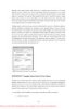
- memory. This should help alleviate memory load and might allow the virtual address allocation to work during the next attempt. (Recall, however, that reclaiming affects only system cache and nonpaged pool). EXPERIMENT: Setting System Virtual address limits The MiSystemVaTypeCountLimit array contains limitations for system virtual address usage that can be set for each type. Currently, the memory manager allows only certain virtual address types to be limited, and it provides the ability to use an undocumented system call to set limits for the system dynamically during run time. (These limits can also be set through the registry, as described at http://msdn.microsoft.com/enus/library/bb870880(VS.85).aspx. These limits can be set for those types marked in Table 9-9. You can use the MemLimit utility from Winsider Seminars & Solutions (www.winsiderss.com /tools/memlimit.html) to query and set the different limits for these types, and also to see the current and peak virtual address space usage. Here’s how you can query the current limits with the –q flag: 1. C:\ >memlimit.exe -q 2. MemLimit v1.00 - Query and set hard limits on system VA space consumption 3. Copyright (C) 2008 Alex Ionescu 4. www.alex-ionescu.com 5. System Va Consumption: 6. Type Current Peak Limit 7. Non Paged Pool 102400 KB 0 KB 0 KB 8. Paged Pool 59392 KB 83968 KB 0 KB 9. System Cache 534528 KB 536576 KB 0 KB 10. System PTEs 73728 KB 75776 KB 0 KB 11. Session Space 75776 KB 90112 KB 0 KB As an experiment, use the following command to set a limit of 100 MB for paged pool: 1. memlimit.exe -p 100M And now try running the testlimit –h experiment from Chapter 3 again, which attempted to create 16 million handles. Instead of reaching the 16 million handle count, the process will fail, because the system will have run out of address space available for paged pool allocations. Finally, as of Windows Vista and Windows Server 2008, the system virtual address space limits apply only to 32-bit systems, where 1 to 2 GB of kernel address space can lead to exhaustion. Sixty-four-bit systems have 8 TB of kernel address space, so limiting virtual address space usage is currently not a concern. 9.5.8 System Virtual Address Space Quotas 692 Please purchase PDF Split-Merge on www.verypdf.com to remove this watermark.
- The system virtual address space limits described in the previous section allow for limiting systemwide virtual address space usage of certain kernel components, but they work only on 32-bit systems when applied to the system as a whole. To address more specific quota requirements that system administrators might have, the memory manager also collaborates with the process manager to enforce either systemwide or user-specific quotas for each process. The PagedPoolQuota, NonPagedPoolQuota, PagingFileQuota, and WorkingSetPagesQuota values in the HKLM\SYSTEM\CurrentControlSet\Control\Session Manager\Memory Management key can be configured to specify how much memory of each type a given process can use. This information is read at initialization, and the default system quota block is generated and then assigned to all system processes (user processes will get a copy of the default system quota block unless per-user quotas have been configured as explained next). To enable per-user quotas, subkeys under the registry key HKLM\SYSTEM\CurrentControl-Set \Session Manager\Quota System can be created, each one representing a given user SID. The values mentioned previously can then be created under this specific SID subkey, enforcing the limits only for the processes created by that user. Table 9-10 shows how to configure these values, which can be configured at run time or not, and which privileges are required. 9.5.9 User Address Space Layout Just as address space in the kernel is dynamic, the user address space in Windows Vista and later versions is also built dynamically—the addresses of the thread stacks, process heaps, and loaded images (such as DLLs and an application’s executable) are dynamically computed (if the application and its images support it) through a mechanism known as Address Space Layout Randomization, or ASLR. At the operating system level, user address space is divided into a few well-defined regions of memory, shown in Figure 9-15. The executable and DLLs themselves are present as memory 693 Please purchase PDF Split-Merge on www.verypdf.com to remove this watermark.
- mapped image files, followed by the heap(s) of the process and the stack(s) of its thread(s). Apart from these regions (and some reserved system structures such as the TEBs and PEB), all other memory allocations are run-time dependent and generated. ASLR is involved with the location of all these regions and, combined with DEP, provides a mechanism for making remote exploitation of a system through memory manipulation harder to achieve—by having code and data at dynamic locations, an attacker cannot typically hardcode a meaningful offset. EXPERIMENT: analyzing user Virtual address Space The Vmmap utility from Sysinternals can show you a detailed view of the virtual memory being utilized by any process on your machine, divided into categories for each type of allocation, summarized as follows: ■ Image Displays memory allocations used to map the process and its dependencies (such as dynamic libraries) and any other memory mapped image files ■ Private Displays memory allocations marked as private, such as internal data structures, other than the stack and heap ■ Shareable Displays memory allocations marked as shareable, typically including shared memory (but not memory mapped files, which are either Image or Mapped File) ■ Mapped File Displays memory allocations for memory mapped data files ■ Heap Displays memory allocated for the heap(s) that this process owns ■ Stack Displays memory allocated for the stack of each thread in this process 694 Please purchase PDF Split-Merge on www.verypdf.com to remove this watermark.
- ■ System Displays kernel memory allocated for the process (such as the process object) The following screen shot shows a typical view of Explorer as seen through Vmmap. Depending on the type of memory allocation, Vmmap can show additional information, such as file names (for mapped files), heap IDs (for heap allocations), and thread IDs (for stack allocations). Furthermore, each allocation’s cost is shown both in committed memory and working set memory. The size and protection of each allocation is also displayed. ASLR begins at the image level, with the executable for the process and its dependent DLLs. Any image file that has specified ASLR support in its PE header (IMAGE_DLL_CHARACTERISTICS_DYNAMIC_BASE), typically specified by using the /DYNAMICBASE linker flag in Microsoft Visual Studio, and contains a relocation section will be processed by ASLR. When such an image is found, the system selects an image offset valid globally for the current boot. This offset is selected from a bucket of 256 values, all of which are 64-KB aligned. Note You can control ASLR behavior by creating a key called MoveImages under HKLM\SYSTEM\CurrentControlSet\Session Manager\Memory Management. Setting this value to 0 will disable ASLR, while a value of 0xFFFFFFFF (–1) will enable ASLR regardless of the IMAGE_DLL_CHARACTERISTICS_DYNAMIC_BASE flag. (Images must still be relocatable, however.) Image Randomization For executables, the load offset is calculated by computing a delta value each time an executable is loaded. This value is a pseudo-random 8-bit number from 0x10000 to 0xFE0000, calculated by taking the current processor’s time stamp counter (TSC), shifting it by four places, and then performing a division modulo 254 and adding 1. This number is then multiplied by the allocation granularity of 64 KB discussed earlier. By adding 1, the memory manager ensures that the value can never be 0, so executables will never load at the address in the PE header if ASLR is being 695 Please purchase PDF Split-Merge on www.verypdf.com to remove this watermark.
- used. This delta is then added to the executable’s preferred load address, creating one of 256 possible locations within 16 MB of the image address in the PE header. For DLLs, computing the load offset begins with a per-boot, systemwide value called the image bias, which is computed by MiInitializeRelocations and stored in MiImageBias. This value corresponds to the time stamp counter (TSC) of the current CPU when this function was called during the boot cycle, shifted and masked into an 8-bit value, which provides 256 possible values. Unlike executables, this value is computed only once per boot and shared across the system to allow DLLs to remain shared in physical memory and relocated only once. Otherwise, if every DLL was loaded at a different location inside different processes, each DLL would have a private copy loaded in physical memory. Once the offset is computed, the memory manager initializes a bitmap called the MiImageBitMap. This bitmap is used to represent ranges from 0x50000000 to 0x78000000 (stored in MiImageBitMapHighVa), and each bit represents one unit of allocation (64 KB, as mentioned earlier). Whenever the memory manager loads a DLL, the appropriate bit is set to mark its location in the system; when the same DLL is loaded again, the memory manager shares its section object with the already relocated information. As each DLL is loaded, the system scans the bitmap from top to bottom for free bits. The MiImageBias value computed earlier is used as a start index from the top to randomize the load across different boots as suggested. Because the bitmap will be entirely empty when the first DLL (which is always Ntdll.dll) is loaded, its load address can easily be calculated: 0x78000000 – MiImageBias * 0x10000. Each subsequent DLL will then load in a 64-KB chunk below. Because of this, if the address of Ntdll.dll is known, the addresses of other DLLs could easily be computed. To mitigate this possibility, the order in which known DLLs are mapped by the Session Manager during initialization is also randomized when Smss loads. Finally, if no free space is available in the bitmap (which would mean that most of the region defined for ASLR is in use, the DLL relocation code defaults back to the executable case, loading the DLL at a 64-KB chunk within 16 MB of its preferred base address. Stack Randomization The next step in ASLR is to randomize the location of the initial thread’s stack (and, subsequently, of each new thread). This randomization is enabled unless the flag StackRandomization Disabled was enabled for the process and consists of first selecting one of 32 possible stack locations separated by either 64 KB or 256 KB. This base address is selected by finding the first appropriate free memory region and then choosing the xth available region, where x is once again generated based on the current processor’s TSC shifted and masked into a 5-bit value (which allows for 32 possible locations). Once this base address has been selected, a new TSC-derived value is calculated, this one 9 bits long. The value is then multiplied by 4 to maintain alignment, which means it can be as large as 2,048 bytes (half a page). It is added to the base address to obtain the final stack base. 696 Please purchase PDF Split-Merge on www.verypdf.com to remove this watermark.
- Heap Randomization Finally, ASLR randomizes the location of the initial process heap (and subsequent heaps) when created in user mode. The RtlCreateHeap function uses another pseudo-random, TSC-derived value to determine the base address of the heap. This value, 5 bits this time, is multiplied by 64 KB to generate the final base address, starting at 0, giving a possible range of 0x00000000 to 0x001F0000 for the initial heap. Additionally, the range before the heap base address is manually deallocated in an attempt to force an access violation if an attack is doing a brute-force sweep of the entire possible heap address range. EXPERIMENT: looking at aSlR Protection on Processes You can use Process Explorer from Sysinternals to look over your processes (and, just as important, the DLLs they load) to see if they support ASLR. To look at the ASLR status for processes, right-click on any column in the process tree, choose Select Columns, and then check ASLR Enabled on the Process Image tab. The following screen shot displays an example of a system on which you can notice that ASLR is enabled for all in-box Windows programs and services but that some third-party applications and services are not yet built with ASLR support. 9.6 Address Translation Now that you’ve seen how Windows structures the virtual address space, let’s look at how it maps these address spaces to real physical pages. User applications and system code reference virtual addresses. This section starts with a detailed description of 32-bit x86 address translation and continues with a brief description of the differences on the 64-bit IA64 and x64 platforms. In the next section, we’ll describe what happens when such a translation doesn’t resolve to a physical memory address (paging) and explain how Windows manages physical memory via working sets and the page frame database. 9.6.1 x86 Virtual Address Translation 697 Please purchase PDF Split-Merge on www.verypdf.com to remove this watermark.
- Using data structures the memory manager creates and maintains called page tables, the CPU translates virtual addresses into physical addresses. Each virtual address is associated with a system-space structure called a page table entry (PTE), which contains the physical address to which the virtual one is mapped. For example, Figure 9-16 shows how three consecutive virtual pages are mapped to three physically discontiguous pages on an x86 system. There may not even be any PTEs for regions that have been marked as reserved or committed but never accessed, because the page table itself might be allocated only when the first page fault occurs. The dashed line connecting the virtual pages to the PTEs in Figure 9-16 represents the indirect relationship between virtual pages and physical memory. Note Kernel-mode code (such as device drivers) can reference physical memory addresses by mapping them to virtual addresses. For more information, see the memory descriptor list (MDL) support routines described in the WDK documentation. By default, Windows on an x86 system uses a two-level page table structure to translate virtual to physical addresses. (x86 systems running the PAE kernel use a three-level page table—this section assumes non-PAE systems.) A 32-bit virtual address mapped by a normal 4-KB page is interpreted as three separate components—the page directory index, the page table index, and the byte index—that are used as indexes into the structures that describe page mappings, as illustrated in Figure 9-17. The page size and the PTE width dictate the width of the page directory and page table index fields. For example, on x86 systems, the byte index is 12 bits because pages are 4,096 bytes (212 = 4,096). 698 Please purchase PDF Split-Merge on www.verypdf.com to remove this watermark.
- The page directory index is used to locate the page table in which the virtual address’s PTE is located. The page table index is used to locate the PTE, which, as mentioned earlier, contains the physical address to which a virtual page maps. The byte index finds the proper address within that physical page. Figure 9-18 shows the relationship of these three values and how they are used to map a virtual address into a physical address. The following basic steps are involved in translating a virtual address: 1. The memory management hardware locates the page directory for the current process. On each process context switch, the hardware is told the address of a new process page directory by the operating system setting a special CPU register (CR3 in Figure 9-18). 2. The page directory index is used as an index into the page directory to locate the page directory entry (PDE) that describes the location of the page table needed to map the virtual address. The PDE contains the page frame number (PFN) of the page table (if it is resident—page tables can be paged out or not yet created). In both of these cases, the page table is first made resident before proceeding. For large pages, the PDE points directly to the PFN of the target page, and the rest of the address is treated as the byte offset within this frame. 3. The page table index is used as an index into the page table to locate the PTE that describes the physical location of the virtual page in question. 4. The PTE is used to locate the page. If the page is valid, it contains the PFN of the page in physical memory that contains the virtual page. If the PTE indicates that the page isn’t valid, the 699 Please purchase PDF Split-Merge on www.verypdf.com to remove this watermark.
- memory management fault handler locates the page and tries to make it valid. (See the section on page fault handling.) If the page should not be made valid (for example, because of a protection fault), the fault handler generates an access violation or a bug check. 5. When the PTE is pointed to a valid page, the byte index is used to locate the address of the desired data within the physical page. Now that you have the overall picture, let’s look at the detailed structure of page directories, page tables, and PTEs. Page Directories Each process has a single page directory, a page the memory manager creates to map the location of all page tables for that process. The physical address of the process page directory is stored in the kernel process (KPROCESS) block, but it is also mapped virtually at address 0xC0300000 on x86 systems (0xC0600000 on systems running the PAE kernel image). Most code running in kernel mode references virtual addresses, not physical ones. (For more detailed information about KPROCESS and other process data structures, refer to Chapter 5.) The CPU knows the location of the page directory page because a special register (CR3 on x86 systems) inside the CPU that is loaded by the operating system contains the physical address of the page directory. Each time a context switch occurs to a thread that is in a different process than that of the currently executing thread, this register is loaded from the KPROCESS block of the target process being switched to by the context-switch routine in the kernel. Context switches between threads in the same process don’t result in reloading the physical address of the page directory because all threads within the same process share the same process address space. The page directory is composed of page directory entries (PDEs), each of which is 4 bytes long (8 bytes on systems running the PAE kernel image) and describes the state and location of all the possible page tables for that process. (If the page table does not yet exist, the VAD tree is consulted to determine whether an access should materialize it.) (As described later in the chapter, page tables are created on demand, so the page directory for most processes points only to a small set of page tables.) The format of a PDE isn’t repeated here because it’s mostly the same as a hardware PTE. On x86 systems running in non-PAE mode, 1,024 page tables are required to describe the full 4-GB virtual address space. The process page directory that maps these page tables contains 1,024 PDEs. Therefore, the page directory index needs to be 10 bits wide (210 = 1,024). On x86 systems running in PAE mode, there are 512 entries in a page table (because the PTE size is 8 bytes and page tables are 4 KB in size). Because there are 4 page directories, the result is a maximum of 2,048 page tables. EXPERIMENT: Examining the Page Directory and PDEs 700 Please purchase PDF Split-Merge on www.verypdf.com to remove this watermark.
- You can see the physical address of the currently running process’s page directory by examining the DirBase field in the !process kernel debugger output: 1. lkd> !process 2. PROCESS 87248070 SessionId: 1 Cid: 088c Peb: 7ffdf000 ParentCid: 06d0 3. DirBase: ce2a8980 ObjectTable: a72ba408 HandleCount: 95. 4. Image: windbg.exe 5. VadRoot 86ed30a0 Vads 85 Clone 0 Private 3474. Modified 187. Locked 1. 6. DeviceMap 98fd1008 7. Token affe1c48 8. ElapsedTime 00:18:17.182 9. UserTime 00:00:00.000 10. KernelTime 00:00:00.000 You can see the page directory’s virtual address by examining the kernel debugger output for the PTE of a particular virtual address, as shown here: 1. lkd> !pte 50001 2. VA 00050001 3. PDE at 00000000C0600000 PTE at 00000000C0000280 4. contains 0000000056C74867 contains 80000000C0EBD025 5. pfn 56c74 ---DA--UWEV pfn c0ebd ----A--UR-V The PTE part of the kernel debugger output is defined in the section “Page Tables and Page Table Entries.” Because Windows provides a private address space for each process, each process has its own set of process page tables to map that process’s private address space. However, the page tables that describe system space are shared among all processes (and session space is shared only among processes in a session). To avoid having multiple page tables describing the same virtual memory, when a process is created, the page directory entries that describe system space are initialized to point to the existing system page tables. If the process is part of a session, session space page tables are also shared by pointing the session space page directory entries to the existing session page tables. Page Tables and Page Table Entries The process page directory entries point to individual page tables. Page tables are composed of an array of PTEs. The virtual address’s page table index field (as shown in Figure 9-17) indicates which PTE within the page table maps the data page in question. On x86 systems, the page table index is 10 bits wide (9 on PAE), allowing you to reference up to 1,024 4-byte PTEs (512 8-byte PTEs on PAE systems). However, because 32-bit Windows provides a 4-GB private virtual address space, more than one page table is needed to map the entire address space. To calculate the number of page tables required to map the entire 4-GB process virtual address space, divide 4 GB by the virtual memory mapped by a single page table. Recall that each page table on an x86 701 Please purchase PDF Split-Merge on www.verypdf.com to remove this watermark.
- system maps 4 MB (2 MB on PAE) of data pages. Thus, 1,024 page tables (4 GB/4 MB)—or 2,048 page tables (4 GB/2 MB) for PAE—are required to map the full 4-GB address space. You can use the !pte command in the kernel debugger to examine PTEs. (See the experiment “Translating Addresses.”) We’ll discuss valid PTEs here and invalid PTEs in a later section. Valid PTEs have two main fields: the page frame number (PFN) of the physical page containing the data or of the physical address of a page in memory, and some flags that describe the state and protection of the page, as shown in Figure 9-19. As you’ll see later, the bits labeled Reserved in Figure 9-19 are used only when the PTE is valid. (The bits are interpreted by software.) Table 9-11 briefly describes the hardwaredefined bits in a valid PTE. On x86 systems, a hardware PTE contains a Dirty bit and an Accessed bit. The Accessed bit is clear if a physical page represented by the PTE hasn’t been read or written since the last time it was cleared; the processor sets this bit when the page is read or written if and only if the bit is 702 Please purchase PDF Split-Merge on www.verypdf.com to remove this watermark.
- clear at the time of access. The memory manager sets the Dirty bit when a page is first written, compared to the backing store copy. In addition to those two bits, the x86 memory management implementation uses a Write bit to provide page protection. When this bit is clear, the page is read-only; when it is set, the page is read/write. If a thread attempts to write to a page with the Write bit clear, a memory management exception occurs, and the memory manager’s access fault handler (described in the next section) must determine whether the thread can write to the page (for example, if the page was really marked copyon-write) or whether an access violation should be generated. The additional Write bit implemented in software (as described above) is used to optimize flushing of the PTE cache (called the translation lookaside buffer, described in the next section). Byte Within Page Once the memory manager has found the physical page in question, it must find the requested data within that page. This is where the byte index field comes in. The byte index field tells the CPU which byte of data in the page you want to reference. On x86 systems, the byte index is 12 bits wide, allowing you to reference up to 4,096 bytes of data (the size of a page). So, adding the byte offset to the physical page number retrieved from the PTE completes the translation of a virtual address to a physical address. 9.6.2 Translation Look-Aside Buffer As you’ve learned so far, each hardware address translation requires two lookups: one to find the right page table in the page directory and one to find the right entry in the page table. Because doing two additional memory lookups for every reference to a virtual address would result in unacceptable system performance, all CPUs cache address translations so that repeated accesses to the same addresses don’t have to be retranslated. The processor provides such a cache in the form of an array of associative memory called the translation lookaside buffer, or TLB. Associative memory, such as the TLB, is a vector whose cells can be read simultaneously and compared to a target value. In the case of the TLB, the vector contains the virtual-to-physical page mappings of the most recently used pages, as shown in Figure 9-20, and the type of page protection, size, attributes, and so on applied to each page. Each entry in the TLB is like a cache entry whose tag holds portions of the virtual address and whose data portion holds a physical page number, protection field, valid bit, and usually a dirty bit indicating the condition of the page to which the cached PTE corresponds. If a PTE’s global bit is set (used for system space pages that are globally visible to all processes), the TLB entry isn’t invalidated on process context switches. 703 Please purchase PDF Split-Merge on www.verypdf.com to remove this watermark.
- Virtual addresses that are used frequently are likely to have entries in the TLB, which provides extremely fast virtual-to-physical address translation and, therefore, fast memory access. If a virtual address isn’t in the TLB, it might still be in memory, but multiple memory accesses are needed to find it, which makes the access time slightly slower. If a virtual page has been paged out of memory or if the memory manager changes the PTE, the memory manager is required to explicitly invalidate the TLB entry. If a process accesses it again, a page fault occurs, and the memory manager brings the page back into memory (if needed) and re-creates its PTE entry (which then results in an entry for it in the TLB). 9.6.3 Physical Address Extension (PAE) The Intel x86 Pentium Pro processor introduced a memory-mapping mode called Physical Address Extension (PAE). With the proper chipset, the PAE mode allows 32-bit operating systems access to up to 64 GB of physical memory on current Intel x86 processors and up to 1,024 GB of physical memory when running on x64 processors in legacy mode (although Windows currently limits this to 64 GB due to the size of the PFN database required to map so much memory). When the processor executes in PAE mode, the memory management unit (MMU) divides virtual addresses mapped by normal pages into four fields, as shown in Figure 9-21. 704 Please purchase PDF Split-Merge on www.verypdf.com to remove this watermark.
- The MMU still implements page directories and page tables, but a third level, the page directory pointer table, exists above them. PAE mode can address more memory than the standard translation mode not because of the extra level of translation but because PDEs and PTEs are 64 bits wide rather than 32 bits. A 32-bit system represents physical addresses internally with 24 bits, which gives the ability to support a maximum of 224+12 bytes, or 64 GB, of memory. One way in which 32-bit applications can take advantage of such large memory configurations is described in the earlier section “Address Windowing Extensions.” However, even if applications are not using such functions, the memory manager will use all available physical memory for multiple processes’ working sets, file cache, and trimmed private data through the use of the system cache, standby, and modified lists (described in the section “Page Frame Number Database”). As explained in Chapter 2, there is a special version of the 32-bit Windows kernel with support for PAE called Ntkrnlpa.exe. This PAE kernel is loaded on 32-bit systems that have hardware support for nonexecutable memory (described earlier in the section “No Execute Page Protection”) or on systems that have more than 4 GB of RAM on an edition of Windows that supports more than 4 GB of RAM (for example, Windows Server 2008 Enterprise Edition). To force the loading of this PAE-enabled kernel, you can set the pae BCD option to ForceEnable. Note that the PAE kernel is present on all 32-bit Windows systems, even systems with small memory without hardware no-execute support. The reason for this is to facilitate device driver testing. Because the PAE kernel presents 64-bit addresses to device drivers and other system code, booting with pae even on a small memory system allows device driver developers to test parts of their drivers with large addresses. The other relevant BCD option is nolowmem, which discards memory below 4 GB (assuming you have at least 5 GB of physical memory) and relocates device drivers above this range. This guarantees that drivers will be presented with physical addresses greater than 32 bits, which makes any possible driver sign extension bugs easier to find. EXPERIMENT: Translating addresses 705 Please purchase PDF Split-Merge on www.verypdf.com to remove this watermark.
- To clarify how address translation works, this experiment shows a real example of translating a virtual address on an x86 PAE system (which is typical on today’s processors, which support hardware no-execute protection, not because PAE itself is actually in use), using the available tools in the kernel debugger to examine page directories, page tables, and PTEs. In this example, we’ll work with a process that has virtual address 0x50001 currently mapped to a valid physical address. In later examples, you’ll see how to follow address translation for invalid addresses with the kernel debugger. First let’s convert 0x50001 to binary and break it into the three fields that are used to translate an address. In binary, 0x50001 is 101.0000.0000.0000.0001. Breaking it into the component fields yields the following: To start the translation process, the CPU needs the physical address of the process page directory, stored in the CR3 register while a thread in that process is running. You can display this address by examining the CR3 register itself or by dumping the KPROCESS block for the process in question with the !process command, as shown here: 1. lkd> !process 2. PROCESS 87248070 SessionId: 1 Cid: 088c Peb: 7ffdf000 ParentCid: 06d0 3. DirBase: ce2a8980 ObjectTable: a72ba408 HandleCount: 95. 4. Image: windbg.exe 5. VadRoot 86ed30a0 Vads 85 Clone 0 Private 3559. Modified 187. Locked 1. 6. DeviceMap 98fd1008 7. Token affe1c48 In this case, the page directory is stored at physical address 0xce2a8980. As shown in the preceding illustration, the page directory index field in this example is 0. Therefore, the PDE is at physical address 0xce2a8980. 706 Please purchase PDF Split-Merge on www.verypdf.com to remove this watermark.
- The kernel debugger !pte command displays the PDE and PTE that describe a virtual address, as shown here: 1. lkd> !pte 50001 2. VA 00050001 3. PDE at 00000000C0600000 PTE at 00000000C0000280 4. contains 0000000056C74867 contains 80000000C0EBD025 5. pfn 56c74 ---DA--UWEV pfn c0ebd ----A--UR-V In the first column the kernel debugger displays the PDE, and in the second column it displays the PTE. Notice that the PDE address is shown as a virtual address, not a physical address—as noted earlier, the process page directory starts at virtual address 0xC0600000 on x86 systems with PAE (in this case, the PAE kernel is loaded because the CPU supports no-execute protection). Because we’re looking at the first PDE in the page directory, the PDE address is the same as the page directory address. The PTE is at virtual address 0xC0000280. You can compute this address by multiplying the page table index (0x50 in this example) by the size of a PTE: 0x50 multiplied by 8 (on a non-PAE system, this would be 4) equals 0x280. Because the memory manager maps page tables starting at 0xC0000000, adding 280 yields the virtual address shown in the kernel debugger output: 0xC0000280. The page table page is at PFN 0x56c74, and the data page is at PFN 0xc0ebd. The PTE flags are displayed to the right of the PFN number. For example, the PTE that describes the page being referenced has flags of --A--UR-V. Here, A stands for accessed (the page has been read), U for user-mode page (as opposed to a kernel-mode page), R for read-only page (rather than writable), and V for valid. (The PTE represents a valid page in physical memory.) 9.6.4 IA64 Virtual Address Translation The virtual address space for IA64 is divided into eight regions by the hardware. Each region can have its own set of page tables. Windows uses five of the regions, three of which have page tables. Table 9-12 lists the regions and how they are used. 707 Please purchase PDF Split-Merge on www.verypdf.com to remove this watermark.
- Address translation by 64-bit Windows on the IA64 platform uses a three-level page table scheme. Each process has a page directory pointer structure that contains 1,024 pointers to page directories. Each page directory contains 1,024 pointers to page tables, which in turn point to physical pages. Figure 9-22 shows the format of an IA64 hardware PTE. 9.6.5 x64 Virtual Address Translation 64-bit Windows on the x64 architecture uses a four-level page table scheme. Each process has a top-level extended page directory (called the page map level 4) that contains 512 pointers to a third-level structure called a page parent directory. Each page parent directory contains 512 pointers to second-level page directories, each of which contain 512 pointers to the individual page tables. Finally, the page tables (each of which contain 512 page table entries) point to pages in memory. Current implementations of the x64 architecture limit virtual addresses to 48 bits. The components that make up this 48-bit virtual address are shown in Figure 9-23. The connections between these structures are shown in Figure 9-24. Finally, the format of an x64 hardware page table entry is shown in Figure 9-25. 708 Please purchase PDF Split-Merge on www.verypdf.com to remove this watermark.
- 9.7 Page Fault Handling Earlier, you saw how address translations are resolved when the PTE is valid. When the PTE valid bit is clear, this indicates that the desired page is for some reason not (currently) accessible to the process. This section describes the types of invalid PTEs and how references to them are resolved. Note Only the 32-bit x86 PTE formats are detailed in this book. PTEs for 64-bit systems contain similar information, but their detailed layout is not presented. A reference to an invalid page is called a page fault. The kernel trap handler (introduced in the section “Trap Dispatching” in Chapter 3) dispatches this kind of fault to the memory manager fault handler (MmAccessFault) to resolve. This routine runs in the context of the thread that incurred the fault and is responsible for attempting to resolve the fault (if possible) or raise an appropriate exception. These faults can be caused by a variety of conditions, as listed in Table 9-13. 709 Please purchase PDF Split-Merge on www.verypdf.com to remove this watermark.
CÓ THỂ BẠN MUỐN DOWNLOAD
-

Windows Internals covering windows server 2008 and windows vista- P1
 50 p |
  130
|
130
|  24
24
-

Windows Internals covering windows server 2008 and windows vista- P2
50 p | 154
| 14
-
Windows Internals covering windows server 2008 and windows vista- P3
50 p | 118
| 13
-
Windows Internals covering windows server 2008 and windows vista- P11
50 p | 116
| 13
-
Windows Internals covering windows server 2008 and windows vista- P6
50 p | 140
| 12
-
Windows Internals covering windows server 2008 and windows vista- P12
50 p | 113
| 11
-

Windows Internals covering windows server 2008 and windows vista- P4
50 p | 134
| 11
-
Windows Internals covering windows server 2008 and windows vista- P5
50 p | 112
| 10
-
Windows Internals covering windows server 2008 and windows vista- P16
50 p | 95
| 10
-

Windows Internals covering windows server 2008 and windows vista- P10
50 p | 125
| 10
-
Windows Internals covering windows server 2008 and windows vista- P7
50 p | 108
| 10
-
Windows Internals covering windows server 2008 and windows vista- P14
50 p | 102
| 9
-
Windows Internals covering windows server 2008 and windows vista- P9
50 p | 89
| 9
-
Windows Internals covering windows server 2008 and windows vista- P8
50 p | 91
| 9
-

Windows Internals covering windows server 2008 and windows vista- P13
50 p | 102
| 8
-
Windows Internals covering windows server 2008 and windows vista- P17
50 p | 101
| 8
-
Windows Internals covering windows server 2008 and windows vista- P18
50 p | 134
| 8


Chịu trách nhiệm nội dung:
Nguyễn Công Hà - Giám đốc Công ty TNHH TÀI LIỆU TRỰC TUYẾN VI NA
LIÊN HỆ
Địa chỉ: P402, 54A Nơ Trang Long, Phường 14, Q.Bình Thạnh, TP.HCM
Hotline: 093 303 0098
Email: support@tailieu.vn
Giấy phép Mạng Xã Hội số: 670/GP-BTTTT cấp ngày 30/11/2015 Copyright © 2022-2032 TaiLieu.VN. All rights reserved.

