


Windows Internals covering windows server 2008 and windows vista- P5
lượt xem 10
download
 Download
Vui lòng tải xuống để xem tài liệu đầy đủ
Download
Vui lòng tải xuống để xem tài liệu đầy đủ
Windows Internals covering windows server 2008 and windows vista- P5: In this chapter, we’ll introduce the key Microsoft Windows operating system concepts and terms we’ll be using throughout this book, such as the Windows API, processes, threads, virtual memory, kernel mode and user mode, objects, handles, security, and the registry.
Bình luận(0) Đăng nhập để gửi bình luận!
Nội dung Text: Windows Internals covering windows server 2008 and windows vista- P5
- Because there are certain operations that drivers should not perform when special kernel APCs are disabled, it makes sense to call KeGetCurrentIrql to check whether the IRQL is APC level or not, which is the only way special kernel APCs could have been disabled. However, because the memory manager makes use of guarded mutexes instead, this check fails because guarded mutexes do not raise IRQL. Drivers should therefore call KeAreAllApcsDisabled for this purpose. This function checks whether special kernel APCs are disabled and/or whether the IRQL is APC level—the sure-fire way to detect both guarded mutexes and fast mutexes. Executive Resources Executive resources are a synchronization mechanism that supports shared and exclusive access, and, like fast mutexes, they require that normal kernel-mode APC delivery be disabled before they are acquired. They are also built on dispatcher objects that are only used when there is contention. Executive resources are used throughout the system, especially in filesystem drivers. Threads waiting to acquire a resource for shared access wait for a semaphore associated with the resource, and threads waiting to acquire a resource for exclusive access wait for an event. A semaphore with unlimited count is used for shared waiters because they can all be woken and granted access to the resource when an exclusive holder releases the resource simply by signaling the semaphore. When a thread waits for exclusive access of a resource that is currently owned, it waits on a synchronization event object because only one of the waiters will wake when the event is signaled. Because of the flexibility that shared and exclusive access offers, there are a number of functions for acquiring resources: ExAcquireResourceSharedLite, ExAcquireResourceExclusive- Lite, ExAcquireSharedStarveExclusive, ExAcquireWaitForExclusive, and ExTryToAcquire- ResourceExclusiveLite. These functions are documented in the WDK. EXPERIMENT: Listing Acquired executive resources The kernel debugger !locks command searches paged pool for executive resource objects and dumps their state. By default, the command lists only executive resources that are currently owned, but the –d option will list all executive resources. Here is partial output of the command: 1. lkd> !locks 2. **** DUMP OF ALL RESOURCE OBJECTS **** 3. KD: Scanning for held locks. 4. Resource @ 0x89929320 Exclusively owned 5. Contention Count = 3911396 6. Threads: 8952d030-01< *> 7. KD: Scanning for held locks....................................... 8. Resource @ 0x89da1a68 Shared 1 owning threads 9. Threads: 8a4cb533-01< *> *** Actual Thread 8a4cb530 Note that the contention count, which is extracted from the resource structure, records the number of times threads have tried to acquire the resource and had to wait because it was already owned. You can examine the details of a specific resource object, including the thread that owns the resource and any threads that are waiting for the resource, by specifying the–v switch and the address of the resource: 190 Please purchase PDF Split-Merge on www.verypdf.com to remove this watermark.
- 1. lkd> !locks -v 0x89929320 2. Resource @ 0x89929320 Exclusively owned 3. Contention Count = 3913573 4. Threads: 8952d030-01< *> 5. THREAD 8952d030 Cid 0acc.050c Teb: 7ffdf000 Win32Thread: fe82c4c0 RUNNING on 6. processor 0 7. Not impersonating 8. DeviceMap 9aa0bdb8 9. Owning Process 89e1ead8 Image: windbg.exe 10. Wait Start TickCount 24620588 Ticks: 12 (0:00:00:00.187) 11. Context Switch Count 772193 12. UserTime 00:00:02.293 13. KernelTime 00:00:09.828 14. Win32 Start Address windbg (0x006e63b8) 15. Stack Init a7eba000 Current a7eb9c10 Base a7eba000 Limit a7eb7000 Call 0 16. Priority 10 BasePriority 8 PriorityDecrement 0 IoPriority 2 PagePriority 5 17. Unable to get context for thread running on processor 1, HRESULT 0x80004001 18. 1 total locks, 1 locks currently held Pushlocks Pushlocks are another optimized synchronization mechanism built on gate objects, and, like guarded mutexes, they wait for a gate object only when there’s contention on the lock. They offer advantages over the guarded mutex in that they can be acquired in shared or exclusive mode. However, their main advantage is their size: a resource object is 56 bytes, but a pushlock is pointer-size. Unfortunately, they are not documented in the WDK and are therefore reserved for use by the operating system (although the APIs are exported, so internal drivers do use them). There are two types of pushlocks: normal and cache-aware. Normal pushlocks require only the size of a pointer in storage (4 bytes on 32-bit systems, and 8 bytes on 64-bit systems). When a thread acquires a normal pushlock, the pushlock code marks the pushlock as owned if it is not currently owned. If the pushlock is owned exclusively or the thread wants to acquire the thread exclusively and the pushlock is owned on a shared basis, the thread allocates a wait block on the thread’s stack, initializes a gate object in the wait block, and adds the wait block to the wait list associated with the pushlock. When a thread releases a pushlock, the thread wakes a waiter, if any are present, by signaling the event in the waiter’s wait block. Because a pushlock is only pointer-sized, it actually contains a variety of bits to describe its state. The meaning of those bits changes as the pushlock changes from being contended to noncontended. In its initial state, the pushlock contains the following structure: ■ 1 lock bit, set to 1 if the lock is acquired ■ 1 waiting bit, set to 1 if the lock is contended and someone is waiting on it 191 Please purchase PDF Split-Merge on www.verypdf.com to remove this watermark.
- ■ 1 waking bit, set to 1 if the lock is being granted to a thread and the waiter’s list needs to be optimized ■ 1 multiple shared bit, set to 1 if the pushlock is shared and currently acquired by more than one thread ■ 28 share count bits, containing the number of threads that have acquired the pushlock As discussed previously, when a thread acquires a pushlock exclusively while the pushlock is already acquired by either multiple readers or a writer, the kernel will allocate a pushlock wait block. The structure of the pushlock value itself changes. The 28 share count bits now become the pointer to the wait block. Because this wait block is allocated on the stack and the header files contain a special alignment directive to force it to be 16-byte aligned, the bottom 4 bits of any pushlock wait-block structure will be all zeros. Therefore, those bits are ignored for the purposes of pointer dereferencing, and instead, the 4 bits shown earlier are combined with the pointer value. Because this alignment removes the share count bits, the share count is now stored in the wait block instead. A cache-aware pushlock adds layers to the normal (basic) pushlock by allocating a pushlock for each processor in the system and associating it with the cache-aware pushlock. When a thread wants to acquire a cache-aware pushlock for shared access, it simply acquires the pushlock allocated for its current processor in shared mode; to acquire a cache-aware pushlock exclusively, the thread acquires the pushlock for each processor in exclusive mode. Other than a much smaller memory footprint, one of the large advantages that pushlocks have over executive resources is that in the noncontended case they do not require lengthy accounting and integer operations to perform acquisition or release. By being as small as a pointer, the kernel can use atomic CPU instructions to perform these tasks (lock cmpxchg is used, which atomically compares and exchanges the old lock with a new lock). If the atomic compare and exchange fails, the lock contains values the caller did not expect (callers usually expect the lock to be unused or acquired as shared), and a call is then made to the more complex contended version. To push performance even further, the kernel exposes the pushlock functionality as inline functions, meaning that no function calls are ever generated during noncontended acquisition—the assembly code is directly in each function. This increases code size slightly, but it avoids the slowness of a function call. Finally, pushlocks use several algorithmic tricks to avoid lock convoys (a situation that can occur when multiple threads of the same priority are all waiting on a lock and no actual work gets done), and they are also self-optimizing: the list of threads waiting on a pushlock will be periodically rearranged to provide fairer behavior when the pushlock is released. Areas in which pushlocks are used include the object manager, where they protect global object manager data structures and object security descriptors, and the memory manager, where they protect Address Windowing Extension (AWE) data structures. Deadlock Detection with Driver Verifier A deadlock is a synchronization issue resulting from two threads or processors holding resources that the other wants and neither yielding what it has. This situation might result in system or process hangs. Driver Verifier, described in Chapter 7 and Chapter 9, has an option to 192 Please purchase PDF Split-Merge on www.verypdf.com to remove this watermark.
- check for deadlocks involving spinlocks, fast mutexes, and mutexes. For information on when to enable Driver Verifier to help resolve system hangs, see Chapter 14. Critical Sections Critical sections are one of the main synchronization primitives that Windows provides to user-mode applications on top of the kernel-based synchronization primitives. Critical sections and the other user-mode primitives we’ll see later have one major advantage over their kernel counterparts, which is saving a round-trip to kernel mode in cases in which the lock is noncontended (which is typically 99% of the time or more). Contended cases will still require calling the kernel, however, because it is the only piece of the system that is able to perform the complex waking and dispatching logic required to make these objects work. Critical sections are able to remain in user mode by using a local bit to provide the main exclusive locking logic, much like a spinlock. If the bit is 0, the critical section can be acquired, and the owner sets the bit to 1. This operation doesn’t require calling the kernel but uses the interlocked CPU operations discussed earlier. Releasing the critical section behaves similarly, with bit state changing from 1 to 0 with an interlocked operation. On the other hand, as you can probably guess, when the bit is already 1 and another caller attempts to acquire the critical section, the kernel must be called to put the thread in a wait state. Critical sections also provide more fine-grained locking mechanisms than kernel primitives. A critical section can be acquired for shared or for exclusive mode, allowing it to function as a multiple-reader (shared), single-writer (exclusive) lock for data structures such as databases. When a critical section is acquired in shared mode and other threads attempt to acquire the same critical section, no trip to the kernel is required because none of the threads will be waiting. Only when a thread attempts to acquire the critical section for exclusive access, or the critical section is already locked by an exclusive owner, will this be required. To make use of the same dispatching and synchronization mechanism we’ve seen in the kernel, critical sections actually make use of existing kernel primitives. A critical section data structure actually contains a kernel mutex as well as a kernel semaphore object. When the critical section is acquired exclusively by more than one thread, the mutex is used because it permits only one owner. When the critical section is acquired in shared mode by more than one thread, a semaphore is used because it allows multiple owner counts. This level of detail is typically hidden from the programmer, and these internal objects should never be used directly. Finally, because critical sections are actually not full-blown kernel objects, they do have certain limitations. The primary one is that you cannot obtain a kernel handle to a critical section, and as such, no security, naming, or other object manager functionality can be applied to a critical section. Two processes cannot use the same critical section to coordinate their operations, nor can duplication or inheritance be used. Condition Variables Condition variables provide a Windows native implementation for synchronizing a set of threads that are waiting on a specific result to a conditional test. While this operation was possible with other user-mode synchronization methods, there was no atomic mechanism to check the 193 Please purchase PDF Split-Merge on www.verypdf.com to remove this watermark.
- result of the conditional test and to begin waiting on a change in the result. This required that additional synchronization be used around such pieces of code. A user-mode thread initializes a condition variable by calling InitializeConditionVariable to set up the initial state. When it wants to initiate a wait on the variable, it can call SleepConditionVariableCS, which uses a critical section (that the thread must have initialized) to wait for changes to the variable. The setting thread must use WakeConditionVariable (or WakeAllConditionVariable) after it has modified the variable (there is no automatic detection mechanism). This call will release the critical section of either one or all waiting threads, depending on which function was used. Before condition variables, it was common to use either a notification event or a synchronization event (recall that these are referred to as auto-reset or manual-reset in the Windows API) to signal the change to a variable such as the state of a worker queue. Waiting for a change required a critical section to be acquired and then released, followed by a wait on an event. After the wait, the critical section would have to be re-acquired. During this series of acquisitions and releases, the thread may have switched contexts, causing problems if one of the threads called PulseEvent (a similar problem to the one that keyed events solve by forcing a wait for the setting thread if there is no waiter). With condition variables, acquisition of the critical section can be maintained by the application while SleepConditionVariableCS is called and be released only after the actual work is done. This makes writing work-queue code (and similar implementations) much simpler and predictable. Internally, conditional variables can be thought of as a port of the existing pushlock algorithms present in kernel mode, with the additional complexity of acquiring and releasing critical sections in the SleepConditionVariableCS API. Conditional variables are pointer-size (just like pushlocks), avoid using the dispatcher (which requires a ring transition to kernel mode in this scenario, making the advantage even more noticeable), automatically optimize the wait list during wait operations, and protect against lock convoys. Additionally, condition variables make full use of keyed events instead of the regular event object that developers would have used on their own, which makes even contended cases more optimized. Slim Reader Writer Locks Although condition variables are a synchronization mechanism, they are not fully primitive locking objects. As we’ve seen, they still depend on the critical section lock, whose acquisition and release uses standard dispatcher event objects, so trips through kernel mode can still happen and callers still require the initialization of the large critical section object. If condition variables share a lot of similarities with pushlocks, slim reader writer (SRW) locks are nearly identical. They are also pointer-size, use atomic operations for acquisition and release, rearrange their waiter lists, protect against lock convoys, and can be acquired both in shared and exclusive mode. Some differences from pushlocks, however, include the fact that SRW locks cannot be “upgraded” or converted from shared to exclusive or vice versa. Additionally, they cannot be recursively acquired. Finally, SRW locks are exclusive to user-mode code, while pushlocks are exclusive to kernel-mode code, and the two cannot be shared or exposed from one layer to the other. 194 Please purchase PDF Split-Merge on www.verypdf.com to remove this watermark.
- Not only can SRW locks entirely replace critical sections in application code, but they also offer multiple-reader, single-writer functionality. SRW locks must first be initialized with InitializeSRWLock, after which they can be acquired or released in either exclusive or shared mode with the appropriate APIs: AcquireSRWLockExclusive, ReleaseSRWLockExclusive, AcquireSRWLockShared, and ReleaseSRWLockShared. Note Unlike most other Windows APIs, the SRW locking functions do not return with a value—instead they generate exceptions if the lock could not be acquired. This makes it obvious that an acquisition has failed so that code that assumes success will terminate instead of potentially proceeding to corrupt user data. The Windows SRW locks do not prefer readers or writers, meaning that the performance for either case should be the same. This makes them great replacements for critical sections, which are writer-only or exclusive synchronization mechanisms. If SRW locks were optimized for readers, they would be poor exclusive-only locks, but this isn’t the case. As a result, the design of the condition variable mechanism introduced earlier also allows for the use of SRW locks instead of critical sections, through the SleepConditionVariableSRW API. Finally, SRW locks also use keyed events instead of standard event objects, so the combination of condition variables and SRW locks results in scalable, pointer-size synchronization mechanisms with very few trips to kernel mode—except in contended cases, which are optimized to take less time and memory to wake and set because of the use of keyed events. Run Once Initialization The ability to guarantee the atomic execution of a piece of code responsible for performing some sort of initialization task—such as allocating memory, initializing certain variables, or even creating objects on demand—is a typical problem in multithreaded programming. In a piece of code that can be called simultaneously by multiple threads (a good example is the DllMain routine, which initializes DLLs) there are several ways of attempting to ensure the correct, atomic, and unique execution of initialization tasks. In this scenario, Windows implements init once, or one-time initialization (also called run once initialization internally). This mechanism allows for both synchronous (meaning that the other threads must wait for initialization to complete) execution of a certain piece of code, as well as asynchronous (meaning that the other threads can attempt to do their own initialization and race) execution. We’ll look at the logic behind asynchronous execution later after explaining the synchronous mechanism. In the synchronous case, the developer writes the piece of code that would normally have executed after double-checking the global variable in a dedicated function. Any information that this routine needs can be passed through the parameter variable that the init-once routine accepts. Any output information is returned through the context variable (the status of the initialization itself is returned as a Boolean). All the developer has to do to ensure proper execution is call InitOnceExecuteOnce with the parameter, context, and run-once function pointer after initializing an InitOnce object with InitOnceInitialize API. The system will take care of the rest. For applications that want to use the asynchronous model instead, the threads call InitOnceBeginInitialize and receive a pending status and the context described earlier. If the 195 Please purchase PDF Split-Merge on www.verypdf.com to remove this watermark.
- pending status is FALSE, initialization has already taken place, and the thread uses the context value for the result. (It’s also possible for the function itself to return FALSE, meaning that initialization failed.) However, if the pending status comes back as TRUE, the thread should now race to be the first to create the object. The code that will follow will perform whatever initialization tasks are required, such as creating some sort of object or allocating memory. When this work is done, the thread calls InitOnceComplete with the result of the work as the context and receives a status. If the status is TRUE, the thread won the race, and the object it created or allocated should be the global object. The thread can now save this object or return it to a caller, depending on the usage. In a more complex scenario when the status is FALSE, this means that the thread lost the race. The thread must now undo all the work it did, such as deleting the object or freeing the memory, and then call InitOnceBeginInitialize again. However, instead of requesting to start a race as it did initially, it uses the INIT_ONCE_CHECK_ONLY flag, knowing that it has lost, and requests the winner’s context instead (for example, the object or memory that had to be created or allocated). This returns another status, which can be TRUE, meaning that the context is valid and should be used or returned to the caller, or FALSE, meaning that initialization failed and nobody has actually been able to perform the work (such as in the case of a lowmemory condition, perhaps). In both cases, the mechanism for run once initialization is similar to the mechanism for condition variables and slim reader writer locks. The init once structure is pointer-size, and inline assembly versions of the SRW acquisition/release code are used for the noncontended case, while keyed events are used when contention has occurred (which happens when the mechanism is used in synchronous mode) and the other threads must wait for initialization. In the asynchronous case, the locks are used in shared mode, so multiple threads can perform initialization at the same time. 3.4 System Worker Threads During system initialization, Windows creates several threads in the System process, called system worker threads, which exist solely to perform work on behalf of other threads. In many cases, threads executing at DPC/dispatch level need to execute functions that can be performed only at a lower IRQL. For example, a DPC routine, which executes in an arbitrary thread context (because DPC execution can usurp any thread in the system) at DPC/dispatch level IRQL, might need to access paged pool or wait for a dispatcher object used to synchronize execution with an application thread. Because a DPC routine can’t lower the IRQL, it must pass such processing to a thread that executes at an IRQL below DPC/dispatch level. Some device drivers and executive components create their own threads dedicated to processing work at passive level; however, most use system worker threads instead, which avoids the unnecessary scheduling and memory overhead associated with having additional threads in the system. An executive component requests a system worker thread’s services by calling the executive functions ExQueueWorkItem or IoQueueWorkItem. Device drivers should only use the latter (because this associates the work item with a Device object, allowing for greater accountability and the handling of scenarios in which a driver unloads while its work item is active). These functions place a work item on a queue dispatcher object where the threads look for 196 Please purchase PDF Split-Merge on www.verypdf.com to remove this watermark.
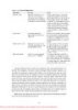
- work. (Queue dispatcher objects are described in more detail in the section “I/O Completion Ports” in Chapter 7.) The IoQueueWorkItemEx, IoSizeofWorkItem, IoInitializeWorkItem, and IoUninitialize- WorkItem APIs act similarly, but they create an association with a driver’s Driver object or one of its Device objects. Work items include a pointer to a routine and a parameter that the thread passes to the routine when it processes the work item. The device driver or executive component that requires passive-level execution implements the routine. For example, a DPC routine that must wait for a dispatcher object can initialize a work item that points to the routine in the driver that waits for the dispatcher object, and perhaps points to a pointer to the object. At some stage, a system worker thread will remove the work item from its queue and execute the driver’s routine. When the driver’s routine finishes, the system worker thread checks to see whether there are more work items to process. If there aren’t any more, the system worker thread blocks until a work item is placed on the queue. The DPC routine might or might not have finished executing when the system worker thread processes its work item. There are three types of system worker threads: ■ Delayed worker threads execute at priority 12, process work items that aren’t considered time-critical, and can have their stack paged out to a paging file while they wait for work items. The object manager uses a delayed work item to perform deferred object deletion, which deletes kernel objects after they have been scheduled for freeing. ■ Critical worker threads execute at priority 13, process time-critical work items, and on Windows Server systems have their stacks present in physical memory at all times. ■ A single hypercritical worker thread executes at priority 15 and also keeps its stack in memory. The process manager uses the hypercritical work item to execute the thread “reaper” function that frees terminated threads. The number of delayed and critical worker threads created by the executive’s ExpWorker-Initialization function, which is called early in the boot process, depends on the amount of memory present on the system and whether the system is a server. Table 3-18 shows the initial number of threads created on default configurations. You can specify that ExpInitializeWorker create up to 16 additional delayed and 16 additional critical worker threads with the AdditionalDelayedWorkerThreads and AdditionalCriticalWorkerThreads values under the registry key HKLM\SYSTEM\CurrentControlSet\Control\Session Manager\Executive. 197 Please purchase PDF Split-Merge on www.verypdf.com to remove this watermark.
- The executive tries to match the number of critical worker threads with changing workloads as the system executes. Once every second, the executive function ExpWorkerThreadBalance- Manager determines whether it should create a new critical worker thread. The critical worker threads that are created by ExpWorkerThreadBalanceManager are called dynamic worker threads, and all the following conditions must be satisfied before such a thread is created: ■ Work items exist in the critical work queue. ■ The number of inactive critical worker threads (ones that are either blocked waiting for work items or that have blocked on dispatcher objects while executing a work routine) must be less than the number of processors on the system. ■ There are fewer than 16 dynamic worker threads. Dynamic worker threads exit after 10 minutes of inactivity. Thus, when the workload dictates, the executive can create up to 16 dynamic worker threads. EXPERIMENT: Listing System Worker Threads You can use the !exqueue kernel debugger command to see a listing of system worker threads classified by their type: 1. lkd> !exqueue 2. Dumping ExWorkerQueue: 820FDE40 3. **** Critical WorkQueue( current = 0 maximum = 2 ) 4. THREAD 861160b8 Cid 0004.001c Teb: 00000000 Win32Thread: 00000000 WAIT 5. THREAD 8613b020 Cid 0004.0020 Teb: 00000000 Win32Thread: 00000000 WAIT 6. THREAD 8613bd78 Cid 0004.0024 Teb: 00000000 Win32Thread: 00000000 WAIT 7. THREAD 8613bad0 Cid 0004.0028 Teb: 00000000 Win32Thread: 00000000 WAIT 8. THREAD 8613b828 Cid 0004.002c Teb: 00000000 Win32Thread: 00000000 WAIT 9. **** Delayed WorkQueue( current = 0 maximum = 2 ) 10. THREAD 8613b580 Cid 0004.0030 Teb: 00000000 Win32Thread: 00000000 WAIT 11. THREAD 8613b2d8 Cid 0004.0034 Teb: 00000000 Win32Thread: 00000000 WAIT 12. THREAD 8613c020 Cid 0004.0038 Teb: 00000000 Win32Thread: 00000000 WAIT 13. THREAD 8613cd78 Cid 0004.003c Teb: 00000000 Win32Thread: 00000000 WAIT 14. THREAD 8613cad0 Cid 0004.0040 Teb: 00000000 Win32Thread: 00000000 WAIT 15. THREAD 8613c828 Cid 0004.0044 Teb: 00000000 Win32Thread: 00000000 WAIT 16. THREAD 8613c580 Cid 0004.0048 Teb: 00000000 Win32Thread: 00000000 WAIT 17. **** HyperCritical WorkQueue( current = 0 maximum = 2 ) 18. THREAD 8613c2d8 Cid 0004.004c Teb: 00000000 Win32Thread: 00000000 WAIT 3.5 Windows global Flags Windows has a set of flags stored in a systemwide global variable named NtGlobalFlag that enable various internal debugging, tracing, and validation support in the operating system. The system variable NtGlobalFlag is initialized from the registry key HKLM\SYSTEM \CurrentControlSet\Control\Session Manager in the value GlobalFlag at system boot time. By 198 Please purchase PDF Split-Merge on www.verypdf.com to remove this watermark.
- default, this registry value is 0, so it’s likely that on your systems, you’re not using any global flags. In addition, each image has a set of global flags that also turn on internal tracing and validation code (although the bit layout of these flags is entirely different from the systemwide global flags). Fortunately, the Windows SDK and the debugging tools contain a utility named Gflags.exe that allows you to view and change the system global flags (either in the registry or in the running system) as well as image global flags. Gflags has both a command-line and a GUI interface. To see the command-line flags, type gflags /?. If you run the utility without any switches, the dialog box shown in Figure 3-25 is displayed. You can configure a variable’s settings in the registry on the System Registry page or the current value of a variable in system memory on the Kernel Flags page. You must click the Apply button to make the changes. (You’ll exit if you click the OK button.) The Image File page requires you to fill in the file name of an executable image. Use this option to change a set of global flags that apply to an individual image (rather than to the whole 199 Please purchase PDF Split-Merge on www.verypdf.com to remove this watermark.
- system). In Figure 3-26, notice that the flags are different from the operating system ones shown in Figure 3-25. EXPERIMENT: Viewing and Setting NtGlobalFlag You can use the !gflag kernel debugger command to view and set the state of the NtGlobalFlag kernel variable. The !gflag command lists all the flags that are enabled. You can use !gflag -? to get the entire list of supported global flags. 1. lkd> !gflag 2. Current NtGlobalFlag contents: 0x00004400 3. ptg - Enable pool tagging 4. otl - Maintain a list of objects for each type 200 Please purchase PDF Split-Merge on www.verypdf.com to remove this watermark.
- 3.6 Advanced Local Procedure Calls (ALPCs) An advanced local procedure call (ALPC) is an interprocess communication facility for highspeed message passing. It is not directly available through the Windows API; it is an internal mechanism available only to Windows operating system components. Here are some examples of where ALPCs are used: ■ Windows applications that use remote procedure calls (RPCs), a documented API, indirectly use ALPCs when they specify local-RPC, a form of RPC used to communicate between processes on the same system. ■ A few Windows APIs result in sending messages to the Windows subsystem process. ■ Winlogon uses ALPCs to communicate with the local security authentication server process, LSASS. ■ The security reference monitor (an executive component explained in Chapter 6) uses ALPCs to communicate with the LSASS process. Note Before ALPCs were introduced in Windows Vista, the kernel supported an IPC mechanism called simply LPC (local procedure call). LPC’s scalability limitations and inherent deadlock scenarios made them a poor choice for the implementation of the User-Mode Driver Framework (UMDF), which requires high-speed, scalable communication with UMDF components in the executive to perform hardware operations. Supporting UMDF was one of the many reasons the ALPC mechanism was written to supplant LPC. (For more information on UMDF, see Chapter 7.) EXPERIMENT: Viewing ALPC Port Objects You can see named ALPC port objects with the WinObj tool from Sysinternals. Run Winobj.exe and select the root directory. A gear icon identifies the port objects, as shown here: 201 Please purchase PDF Split-Merge on www.verypdf.com to remove this watermark.
- To see the ALPC port objects used by RPC, select the \RPC Control directory, as shown here: 202 Please purchase PDF Split-Merge on www.verypdf.com to remove this watermark.
- Typically, ALPCs are used between a server process and one or more client processes of that server. An ALPC connection can be established between two user-mode processes or between a kernel-mode component and a user-mode process. For example, as noted in Chapter 2, Windows processes send occasional messages to the Windows subsystem by using ALPCs. Also, some system processes use ALPCs to communicate, such as Winlogon and Lsass. An example of a kernel-mode component using an ALPC to talk to a user process is the communication between the security reference monitor and the Lsass process. ALPCs support the following three methods of exchanging messages: ■ A message that is shorter than 256 bytes can be sent by calling the ALPC with a buffer containing the message. This message is then copied from the address space of the sending process into system address space, and from there to the address space of the receiving process. ■ If a client and a server want to exchange more than 256 bytes of data, they can choose to use a shared section to which both are mapped. The sender places message data in the shared section and then sends a small message to the receiver with pointers to where the data is to be found in the shared section. 203 Please purchase PDF Split-Merge on www.verypdf.com to remove this watermark.
- ■ When a server wants to read or write larger amounts of data than will fit in a shared section, data can be directly read from or written to a client’s address space. An ALPC exports a single executive object called the port object to maintain the state needed for communication. Although an ALPC uses a single ALPC port object, it has several kinds of ports: ■ Server connection port A named port that is a server connection request point. Clients can connect to the server by connecting to this port. ■ Server communication port An unnamed port a server uses to communicate with a particular client. The server has one such port per active client. ■ Client communication port An unnamed port a particular client thread uses to communicate with a particular server. ALPCs are typically used as follows: A server creates a named server connection port object. A client makes a connect request to this port. If the request is granted, two new unnamed ports, a client communication port and a server communication port, are created. The client gets a handle to the client communication port, and the server gets a handle to the server communication port. The client and the server will then use these new ports for their communication. ALPC supports several features and behaviors that offer communication abilities for processes. For example, applications can create their own sections to associate with an ALPC port and manage (create and delete) views of the section. As mentioned earlier, when a server wants to read or write larger amounts of data than will fit in a shared section, data can be directly read from or written to a client’s address space. The ALPC component supplies two functions that a server can use to accomplish this. A message sent by the first function is used to synchronize the message passing. Another option is to create a message zone, a lockeddown buffer in system memory that will never be paged out and allows messages to be copied back and forth without attaching to the correct process, which is useful when using the I/O completion port feature described later. Yet a third capability in terms of memory requirements is to request the kernel to reserve ALPC resources so that messages can still be delivered during low-memory situations (such messages may be critical to solving or notifying the kernel about the situation in the first place). From a throughput and performance point of view, ALPC ports can be configured to perform work over an I/O completion port instead of the typical request/reply synchronous wait mechanism that LPCs use. This allows for large-scale communication to occur, and the ALPC port object will automatically balance the number of messages and threads for highspeed communication. Additionally, ALPC messages can be batched together so that multiple replies and requests can be sent, minimizing trips from user to kernel mode and vice versa. Finally, apart from limits on message data and header size, applications can also set bandwidth limits and maximum section, view, and pool usage. The ALPC mechanism is also secured. ALPC objects are managed by the same object manager interfaces that manage object security, and secure ports can be created, allowing only a specific SID to use them. Applications can also easily get a handle to the sender thread (and process) of an ALPC message to perform actions such as impersonation. Furthermore, applications have fine control over the security context associated with an ALPC port—for 204 Please purchase PDF Split-Merge on www.verypdf.com to remove this watermark.
- example, they can set and query per-message SID information, as well as test for changes in the security context of a token associated with the ALPC message.ALPC messages can be fully logged and traced to any thread participating in ALPC communications. Additionally, new Event Tracing for Windows (ETW) messages and logging can be enabled for IT administrators and troubleshooters to monitor ALPC messages. A completed connection between a client and a server is shown in Figure 3-27. 3.7 Kernel event Tracing Various components of the Windows kernel and several core device drivers are instrumented to record trace data of their operations for use in system troubleshooting. They rely on a common infrastructure in the kernel that provides trace data to the user-mode Event Tracing for Windows (ETW) facility. An application that uses ETW falls into one or more of three categories: ■ Controller A controller starts and stops logging sessions and manages buffer pools. 205 Please purchase PDF Split-Merge on www.verypdf.com to remove this watermark.
- ■ Provider A provider defines GUIDs (globally unique identifiers) for the event classes it can produce traces for and registers them with ETW. The provider accepts commands from a controller for starting and stopping traces of the event classes for which it’s responsible. ■ Consumer A consumer selects one or more trace sessions for which it wants to read trace data. They can receive the events in buffers in real-time or in log files. Windows Server systems include several built-in providers in user mode, including ones for Active Directory, Kerberos, and Netlogon. ETW defines a logging session with the name NT Kernel Logger (also known as the kernel logger) for use by the kernel and core drivers. The provider for the NT Kernel Logger is implemented by the ETW code in Ntoskrnl.exe and by the core drivers sending traces. When a controller in user mode enables the kernel logger, the ETW library, which is implemented in \Windows\System32\Ntdll.dll, calls the NtTraceControl system call, telling the ETW code in the kernel which event classes the controller wants to start tracing. If file logging is configured (as opposed to in-memory logging to a buffer), the kernel creates a system thread in the system process that creates a log file. When the kernel receives trace events from the enabled trace sources, it records them to a buffer. If it was started, the file logging thread wakes up once per second to dump the contents of the buffers to the log file. Trace records generated for the kernel logger have a standard ETW trace event header, which records time stamp, process, and thread IDs, as well as information on what class of event the record corresponds to. Event classes can provide additional data specific to their events. For example, disk event class trace records indicate the operation type (read or write), disk number at which the operation is directed, and sector offset and length of the operation. The trace classes that can be enabled for the kernel logger and the component that generates each class include: ■ Disk I/O Disk class driver ■ File I/O File system drivers ■ File I/O Completion File system drivers ■ Hardware Configuration Plug and Play manager (See Chapter 7 for information on the Plug and Play manager.) ■ Image Load/Unload The system image loader in the kernel ■ Page Faults Memory manager (See Chapter 9 for more information on page faults.) ■ Hard Page Faults Memory manager ■ Process Create/Delete Process manager (See Chapter 5 for more information on the process manager.) ■ Thread Create/Delete Process manager ■ Registry Activity Configuration manager (See “The Registry” section in Chapter 4 for more information on the configuration manager.) 206 Please purchase PDF Split-Merge on www.verypdf.com to remove this watermark.
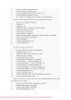
- ■ Network TCP/IP TCP/IP driver ■ Process Counters Process manager ■ Context Switches Kernel dispatcher ■ Deferred Procedure Calls Kernel dispatcher ■ Interrupts Kernel dispatcher ■ System Calls Kernel dispatcher ■ Sample Based Profiling Kernel dispatcher and HAL ■ Driver Delays I/O manager ■ ALPC Advanced local procedure call You can find more information on ETW and the kernel logger, including sample code for controllers and consumers, in the Windows SDK. EXPERIMENT: Tracing TCP/iP Activity with the Kernel Logger To enable the kernel logger and have it generate a log file of TCP/IP activity, follow these steps: 1. Run the Reliability and Performance Monitor, and click on Data Collector Sets, User Defined. 2. Right-click on User Defined, choose New, and select Data Collector Set. 3. When prompted, enter a name for the data collector set (for example, experiment), and choose Create Manually (Advanced). 4. In the dialog box that opens, select Create Data Logs, check Event Trace Data, and then click Next. In the Providers area, click Add, and locate Windows Kernel Trace. In the Properties list, select Keywords(Any), and then click Edit. 207 Please purchase PDF Split-Merge on www.verypdf.com to remove this watermark.
- 5. From this list, check only Net for Network TCP/IP, and then click OK. 208 Please purchase PDF Split-Merge on www.verypdf.com to remove this watermark.
- 6. Select a location to save the files. By default, this location is C:\Perflogs\experiment\, if this is how you named the data collector set. Click Next, and in the Run As edit box, enter the Administrator account name and set the password to match it. Click Finish. You should now see a window similar to the one shown here: 7. Right-click on “experiment” (or whatever name you gave your data collector set), and then click Start. Now generate some network activity by opening a browser and visiting a Web site. 8. Right-click on the data collector set node again, and then click Stop. 9. Open a command prompt, and change to the C:\Perflogs\experiment\00001 directory (or the directory into which you specified that the trace log file be stored). 10. Run tracerpt and pass it the name of the trace log file: tracerpt DataCollector01.etl –o dumpfile.csv –of CSV 11. Open dumpfile.csv in Microsoft Excel or in a text editor. You should see TCP and/or UDP trace records like the following: 1. TcpIp SendIPV4 0xFFFFFFFF 1.28663E+17 0 0 1992 1388 157.54.86.28 172.31.234.35 80 49414 646659 646661 2. UdpIp RecvIPV4 0xFFFFFFFF 1.28663E+17 0 0 4 50 172.31.239.255 172.31.233.110 137 137 0 0x0 3. UdpIp RecvIPV4 0xFFFFFFFF 1.28663E+17 0 0 4 50 172.31.239.255 172.31.234.162 137 137 0 0x0 4. TcpIp RecvIPV4 0xFFFFFFFF 1.28663E+17 0 0 1992 1425 157.54.86.28 172.31.234.35 80 49414 0 0x0 5. TcpIp RecvIPV4 0xFFFFFFFF 1.28663E+17 0 0 1992 1380 157.54.86.28 209 Please purchase PDF Split-Merge on www.verypdf.com to remove this watermark.
CÓ THỂ BẠN MUỐN DOWNLOAD
-

Windows Internals covering windows server 2008 and windows vista- P1
 50 p |
  130
|
130
|  24
24
-

Windows Internals covering windows server 2008 and windows vista- P2
50 p | 154
| 14
-

Windows Internals covering windows server 2008 and windows vista- P3
50 p | 118
| 13
-

Windows Internals covering windows server 2008 and windows vista- P11
50 p | 116
| 13
-
Windows Internals covering windows server 2008 and windows vista- P6
50 p | 140
| 12
-

Windows Internals covering windows server 2008 and windows vista- P4
50 p | 134
| 11
-

Windows Internals covering windows server 2008 and windows vista- P12
50 p | 113
| 11
-

Windows Internals covering windows server 2008 and windows vista- P16
50 p | 95
| 10
-

Windows Internals covering windows server 2008 and windows vista- P15
50 p | 112
| 10
-

Windows Internals covering windows server 2008 and windows vista- P10
50 p | 125
| 10
-

Windows Internals covering windows server 2008 and windows vista- P7
50 p | 108
| 10
-

Windows Internals covering windows server 2008 and windows vista- P9
50 p | 89
| 9
-

Windows Internals covering windows server 2008 and windows vista- P14
50 p | 102
| 9
-

Windows Internals covering windows server 2008 and windows vista- P8
50 p | 91
| 9
-

Windows Internals covering windows server 2008 and windows vista- P13
50 p | 102
| 8
-
Windows Internals covering windows server 2008 and windows vista- P17
50 p | 101
| 8
-

Windows Internals covering windows server 2008 and windows vista- P18
50 p | 134
| 8


Chịu trách nhiệm nội dung:
Nguyễn Công Hà - Giám đốc Công ty TNHH TÀI LIỆU TRỰC TUYẾN VI NA
LIÊN HỆ
Địa chỉ: P402, 54A Nơ Trang Long, Phường 14, Q.Bình Thạnh, TP.HCM
Hotline: 093 303 0098
Email: support@tailieu.vn
Giấy phép Mạng Xã Hội số: 670/GP-BTTTT cấp ngày 30/11/2015 Copyright © 2022-2032 TaiLieu.VN. All rights reserved.

